Ashdown Peacemaker. Overheated resistors, burned PCB, bulging cap, valves run WAY out of spec
No thanks!
Yes. Something very common now : this is what I call poor design... You also see this in Audio tube amps too.
I had for repair an Ashdown BTA-400, which burned a complete set of 8x KT88 by a failure in the screen and bias circuit... Supposed to protect the final stage !
I do not have the pics here, but it was a disaster.
Another brand prone to PSU failure : Engl, and their 0.3mm untinned PCB traces throughout the circuit to supply 450V to the output stage (6L6 duets or quartets).
What about the Blackstar amps with their EL34 duet filaments wired in serie on 12.6V ? This tube is not convenient for serial heater operation, so they die prematurely by filament imbalance voltage (mainly at the start) which led to overload and cut. Excess of simulation, absence of tests or ignorance... Or all three ?
Today, I mainly concentrate on servicing / repairing / restoring / rebuilding vintage-era circuits (no matter the brand) - I'll post some nice pics... 😉
Now I stay away from Marshall JVM and JCM2000 and-the-like "Gas Factories" (Usines à Gaz, as we say in French), if you see what I mean...
T

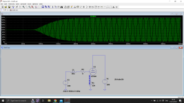
V5 and V6 (DA 100) probably operates in Class AB2 if not in Class B, where the grids become positive. The driver stage provides power to the output stage which show a grid current. This explains the presence of transformers to allow grid current to flow, and the absence of serial resistors which would increase bias with grid current flow and forbid a full class B operation.
That said, I doubt that V3 and V4 (KT66) works over a class A or AB1 operation, hence their cathode bias R14 and R9 R10 grid serie resistors, so there's no grid current expected from them. Again, for me, these are nothing else than oscillation taming resistors, as usual.
T
That said, I doubt that V3 and V4 (KT66) works over a class A or AB1 operation, hence their cathode bias R14 and R9 R10 grid serie resistors, so there's no grid current expected from them. Again, for me, these are nothing else than oscillation taming resistors, as usual.
T
Oscillation will arise at current peaks (higher gm) whether Class A, AB1, AB2 etc. If a grid stopper is needed to prevent oscillation, it will be needed here just as much. But there is none!
The only difference is that blocking distortion is not a problem, with transformer coupling.
The only difference is that blocking distortion is not a problem, with transformer coupling.
You must be joking.Not to mention you are not going to overload a negative feedback amplifier. Which most of them are.
Guitar amps are routinely overloaded, often by 20dB or more.
Specially Marshalls.
Oh, they DO use NFB
ALL of them.
You should investigate a little before posting your wild claims.
What normally passes as "Guitar amp design" nowadays is just endless rehashing of the same 2 or 3 old classic designs.Sorry, I do not do much complicated calculations when I design and build mine...
https://guilhemamplification.jimdofree.com/
T
If not plain "photocopying".
Absolutely no Math required for that
I see a faithful Dumble ODS clone, which in due time was a modded Fender amp.
Shares 90% (or more) of its DNA.
If you want to design, you'll have to bring out datasheets, ruler and pencil for graphical design and a slide rule for the Math side of things.
At least that's how they were designed in the 40s 50s and 60s
That's how I designed in the late 60s, no calculators widely available way back then, until I bought a Bowmar in 70 something.
Until then I had to rely on my trusty Staedtler slide rule, which I keep somewhere.
Or that it's tolerated, in a less demanding application. di/dt ringing of the coupling transformer is likely enough to swamp other issues, esp. if performance is only measured at full output. These very, very non-monotonic designs are historical artifacts and not really useful for music in any modern context. Nobody would do that stuff today - especially Rod Coleman. We've drifted far from shore of the original intent? Damp negative resistance - check - lunch.The only difference is that blocking distortion is not a problem, with transformer coupling.
All good fortune,
Chris
Su
Please read what's written.
Suppressing and creating are not the same thing.That type of resistor suppress rf noise. Are you too spurious in the closed mind that you display for this to sink in?
Please read what's written.
Certainly not!Nobody would do that stuff today -
But a demonstration that power valves can (always could) run zero-stopper without oscillation is the value of this example.
I have, BTW , zero Rg on my SE amplifier end stage, and it always survives the acceptance test (of a sniffer loop connected to my 1GHz spectrum analyser).
We have to go back to primary sources for calibration as the general understanding of self-oscillation has become diffused and confused.
But values of 10k and even higher are much too high for stopper duty, even considering the high leakage inductance of old trannies.
Control of blocking distortion explains this mystery perfectly well, and I present it for your entertainment.
I would only add the caveat that for the general case of homebrew (no grid current) audio amplifiers, the safe guaranteed-to-not-surprise go-to answer is to stick a 1k Ohm resistor on every grid socket. Advanced experimenters, or commercial designers, can go back and remove them on a case by case basis, but the details of how-the-negative-resistance-occurs is too obscure for us plebes, too many unknowns, and a simple brute force insurance policy, I contend, is most appropriate for diyAudio. Guitar amps are their own voudou, of course.
All good fortune,
Chris
All good fortune,
Chris
I expect valve RF oscillation stoppers to be around 300 Ohm. Modern resistor types in moderate values are close to ideal for RF behaviour to 1 GHz and beyond
For sure that tube amps needs grid stopper resistors , especialy for output power tubes in high power PP amps, both for g1 and g2 , and connected directly to socket terminals , also it is not bad to add 10 Ohm/1% resistors from each K/g3 socket terminal connected to minus/earth common lead , just to made good bias level individual test points ,
btw, IMHO good guitar tube amps need to be made using only turet boards and not any PCB , same as is done in old Fender-s and Marshall-s,
here`s my DIY asembled turet board for one future Marshall 100W S.L. replika which use only very selected pasive elements , Iskra resistors & Philips blok condensers , Iskra turet board .
Attachments

Last edited:
I expect valve RF oscillation stoppers to be around 300 Ohm. Modern resistor types in moderate values are close to ideal for RF behaviour to 1 GHz and beyond
For what it's worth, the Pilot ACE valve computer had 47 ohm grid stoppers everywhere and had no oscillation issues. It used current steering valve logic.
Compare this with the Radio Society of Great Britain - RSGB Radio Communication handbook - their suggestions for suppressing oscillations in power amplifiers: (paperback edition 1982, pp 6.38)
Preferred: 5-10Ω wirewound resistor (or VHF RFC) in the anode;
2nd choice: Ferrite bead in the G2 lead;
3rd choice: 10-47Ω carbon resistor in the G1 lead.
This is in keeping with the J. Miller Note - the section giving low values of negative (Real part) of input impedance for stages with inductive anode loads.
Higher values an be used, of course, except when we want to drive grid current. Ferrite beads (modern EMC grade type) in the G1 lead solve this problem, and allow near-zero ohms at AF.
Higher values of 10k or a little more are also suitable, if the stage is at risk of blocking distortion;
but I think that design of good amplifiers is improved by knowledge of exactly why a particular value of resistor is chosen for this position.
but I think that design of good amplifiers is improved by knowledge of exactly why a particular value of resistor is chosen for this position.
Grid stop function is always the same, but some people do get it mixed up with dc coupling input resistor.
I can show everyone the formulas for this.
That reminds me of the Brook 10C circuit but, curiously, it does use grid stoppers in front of the cathode followers. Maybe it's for filtering out high frequency with the two .001uf caps.But check this one without RC coupling - no series resistor, no stopper:

Yes its normally OK if the grid comes from a plate, but those .001 to ground if the grid wiring was long... Maybe the saviour is the old electrolytic on the plate who knows.
Interesting circuit - servo bias. Diode for negative supply is wrong way round I think.
Last edited:
Yes, the diode orientation is wrong. There's another schematic that uses tube rectifier that got it right.Diode for negative supply is wrong way round I think.
- Home
- Amplifiers
- Tubes / Valves
- Does audiophile tube builders know what a grid stop is for?