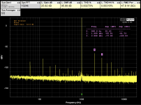
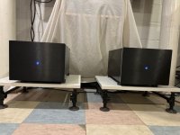
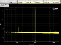
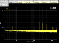
I've finally finished the XA252 (mosfet version) and tried measuring my implementation. As you can see from the measurements, the maximum power I'm getting is around 75W before THD rises significantly.
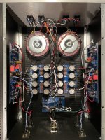
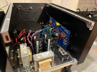
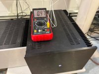
With ~41 VDC rails, Iq = 1.62 A, I'm measuring the heat sinks at about 58 C, and the case of the mosfet pucks about 60 C (ambient ~23 C, Hifi2000 5U/500 chassis with the lid closed).
I'm using two Hammond 1182 series 30VACx2 transformers, and the reason that I'm getting such high rails is that we have 125VAC at the wall socket here. The Hammonds aren't too happy about that and give a faint buzz (coming from the transformers, not the speakers). My next step is to set up a buck transformer to bring the input voltage back to around 115VAC and see if that helps with the buzzing.
I seem to recall that there were some questions earlier in the thread about using a differential input versus single ended while maintaining a dominant 2nd harmonic distortion. These measurements are done with a differential input over a balanced cable from the QA403 and seem to show that the dominant 2nd harmonic is maintained. The caveat: I'm still quite new to measuring. I'm therefore not 100% certain that my measuring setup is optimal.
As you can see, I have some PSU noise that I just couldn't get rid of. I initially adhered to the AES way of connecting the differential inputs. I first tried pin 1 unconnected, then pin 1 connected directly to the chassis, then pin 1 connected to the chassis via a 10 nF capacitor and then via a resistor. In all instances, the PSU noise was much worse, until I just connected pin 1 to the amplifier board, and that reduced the PSU noise to what is shown in the measurements. I've attempted to make sure that my grounding scheme is as optimized as possible, but I'm still not pleased with the wire management. Any suggestions are welcomed!
I haven't done any real listening to the amp yet. That's coming a little later this evening and in the coming days.
Paul
Attachments

decrease Iq; say 1A4; it'll not decrease A Class envelope significantly, but it will cut some edge of working temperature
wiring - in your case - without using base plate:
take old VGA cable and butcher it for screen; dress mains wires through that screen all the way from back side to Donuts; heatshrink it in entire length, solder screen to safety GND on back side, not on Donut side
lay that screened cable to bottom, then you can lay DC wired from bridges on top of it
now - -wires from bridges to cap banks - do not braid them, twist them instead; you have 2 wires from one bridge, two from second bridge (speaking of one channel); twist them all 4 together, lay down on mains cable, going to cap bank pcb
do the same for second channel
same goes for input triplet wires - twist them, not braid ...... or use thin (2+screen) coax
if you don't have old VGA cable to butcher - improvise to find appropriate screen
My XA252 has been plugged in providing enjoyment for a month. And I am happy. Mikerodrig27 summed up perfectly the sound of the XA252 in post #652. I will add, listening to Jimmy Hendrix through this amp is an experience. The sound of overdriven tubes breaking up 12” paper cone drivers is intoxicating.
My diy Troels designed SBA-761 speakers have a polite sound through my SissySIT and diyaudio F6, casting a wide sound stage, beautiful imaging, well balanced bass. The XA252 brings all of that with greater intensity and a you are in the room with the musicians kind of presence.
After extensive listening in both SE and Balanced modes with my diy carl_huff Doug Self Preamp from Linear Audio #5, I am leaning hard toward favoring SE. Balanced mode offers a fierce amount of gain but loses that spoonful of sugar present with SE. The amp is dead quiet in either mode.
Okay, so here are some details about my build:
Full MOS. Substituted IXFN140N20P for IXFN140N30P due to availability. PSU CLC. Antek 4428, 4 x 33,000uF, Hammond 159ZJ 10mH 5A. BFF=22R. Iq=1A8. Chassis are Mini Dissipante 5U 400mm modified to monoblock configuration - aluminum panel replaces one heatsink, 10mm front panel narrowed.
Lastly, the XA252 is one hot tamale. In my 19°c room the heatsinks reach just shy of 50°c after a half hour. The amp sounds its best after warming up for about an hour.
Zen! The XA252 is one superb amplifier. And as I built them, two superb monoblocks.
Attachments
Does your signal ground have a ground lift to chassis ground?…As you can see, I have some PSU noise that I just couldn't get rid of...
decrease Iq; say 1A4; it'll not decrease A Class envelope significantly, but it will cut some edge of working temperature
wiring - in your case - without using base plate:
take old VGA cable and butcher it for screen; dress mains wires through that screen all the way from back side to Donuts; heatshrink it in entire length, solder screen to safety GND on back side, not on Donut side
lay that screened cable to bottom, then you can lay DC wired from bridges on top of it
now - -wires from bridges to cap banks - do not braid them, twist them instead; you have 2 wires from one bridge, two from second bridge (speaking of one channel); twist them all 4 together, lay down on mains cable, going to cap bank pcb
do the same for second channel
same goes for input triplet wires - twist them, not braid ...... or use thin (2+screen) coax
if you don't have old VGA cable to butcher - improvise to find appropriate screen
Would you recommend that I decrease Iq or decrease rails?
Thank you for the suggestion on the shielding. I don't have any sacrificial cable that would have a screen with an appropriate diameter, but I seem think a braided shield could be found online. The secondaries are twisted pairs, 1 pair from each bridge. Only the signal input wires are braided, which I will undo right away.
Does your signal ground have a ground lift to chassis ground?
Yes: I have a star ground (drilled and soldered a nut on each PSU board, on the "clean side of the PSU). From there I have 1 wire going to amp board GND, 1 wire to speaker GND, and 1 wire to a thermistor and then to the chassis. Finally, the soft-start GND is also connected to the chassis via another thermistor (that also further reduced some of the mains noise). There is no other GND (PSU or signal GND) that is connected directly to the chassis. Safety earth is connected directly from the mains connector to the chassis.
My signal chain is all differential up to the amp output, but you got me curious about feeding it a single ended signal. Now that the amp is back on the bench, I'll measure it with a SE source and see how that compares (I would assume less 3rd harmonic?).
Paul
Try replacing the thermistors with bridge rectifiers as ground lifts. Short the DC (+-) terminals, and attach your grounds to the AC terminals, signal grounds to one terminal and chassis ground to the other. See if that eliminates the PSU noise.
In addition to ZM's suggestions, I suggest:
- rotate the toroid transformers to find an orientation of lowest 60Hz noise
- it looks like you power supply capacitors are 10mF. I believe the typical First Watt supply uses 15mF. Some builders use 22mF. I do that and also use a CLC filter instead of a CRC filter. Both will make a difference in the level of the 120Hz noise. My speakers are 103dB sensitive and the difference is audible.
When I check my amplifiers for noise, I measure the noise relative to a 1W @ 8R fundamental signal. That way the signal to noise is comparable between all of my noise measurements. I do not have a QuantAsylum device so I am not familiar with its workings. But with my Focusrite/REW rig, I have a resistor based attenuator to prevent overloading the Focusrite, so the 1W @ 8R is a convenient way to get difference in signal to noise levels that are comparable from amplifier to amplifier.
Would you recommend that I decrease Iq or decrease rails?
at least for starters, decrease Iq; easier than buying new Donuts
as I said, no big deal
regarding capacitance in Cap Bank - more is merrier and think of at least 40something mF per rail per channel, for this amp
I've made the modifications that were suggested: shielded the main wires to the transformers, twists instead of braids for the input wires, and I've tried the bridge instead of the thermistor for the ground lift (somehow it measured a little worse). As for rotating the transformers, I've painted myself in a corner by cutting the secondary wires short. I recall reading that the worst is having the section where the wires come out of the transformer close to the circuits?
I've also decreased Iq to 1.4 A. It's obviously a little less toasty, but still quite hot!
As for the capacitor bank, I currently have 40 mF per rail x4. I initially used PSUD2 to see if 40 mF was enough and to make sure that the ripple current rating of the capacitors I had was adequate for this amp. I can add a few more 10 mF caps, but I need to make a bigger PSU PCB to fit them (much cheaper than bigger caps).
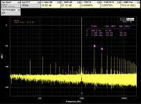
With all the changes, it looks like I've decreased mains noise by about 10 dBV and got rid of most of the mains harmonics. How low should I expect to be able to get the mains noise in this amp?
Paul
I've also decreased Iq to 1.4 A. It's obviously a little less toasty, but still quite hot!
As for the capacitor bank, I currently have 40 mF per rail x4. I initially used PSUD2 to see if 40 mF was enough and to make sure that the ripple current rating of the capacitors I had was adequate for this amp. I can add a few more 10 mF caps, but I need to make a bigger PSU PCB to fit them (much cheaper than bigger caps).
With all the changes, it looks like I've decreased mains noise by about 10 dBV and got rid of most of the mains harmonics. How low should I expect to be able to get the mains noise in this amp?
Paul
Attachments

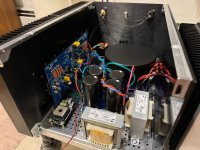
Do these toroidy have goss bands? If not, you can install some grounded steel plate around them to shield them. The plate would ideally cover the whole internal height of the enclosure.
The wiring between transformers and psu caps should be quite short. And I would have chosen thicker wires from the rectifiers to caps connections.
The wiring between transformers and psu caps should be quite short. And I would have chosen thicker wires from the rectifiers to caps connections.
more or less, you're there ....... whatever you do now will gain a little and you can make a difference only perfecting, if possible, all mentioned details
one thing I can't really see - shield for mains wires is connected at back plate side to safety GND potential?
one thing I can't really see - shield for mains wires is connected at back plate side to safety GND potential?
The noise level is looking quite good now. I don't know whether this will make a difference or not, but try moving the input wires tight to the back and side of the chassis, away from the AC wires.
Also I see that the AC wires from the AC input to the Soft Start board is not shield. Shielding may perhaps gain a bit more, especially for the left channel which is closest to the wires.
Also I see that the AC wires from the AC input to the Soft Start board is not shield. Shielding may perhaps gain a bit more, especially for the left channel which is closest to the wires.
One thing I do lately on my monoblocks is rather than tie the ground lift (CL-60) to the power supply ground, as you have it.... I tie it instead to my input RCA jack ground (well within a couple of inches since my front end is mounted with standoffs over the top of the RCA on the back wall). I had room to solder a 90 degree male Faston to the rear of the pcb to make the attachment point. I haven't tried to measure anything but it's silent as a tomb for sure.
Fugly! Fugly!I will add,
(just in case- twice - you have monoblocks)

I realized after the fact that I should probably have placed the rectifiers closer to the PSU board (in between the transformers and PSU) so as to require shorter wires. Those wires are in fact 16 awg, but they look thinner because of the thinner PTFE insulation (it's the PTFE hook-up wires from ApexJr).Do these toroidy have goss bands? If not, you can install some grounded steel plate around them to shield them. The plate would ideally cover the whole internal height of the enclosure.
The wiring between transformers and psu caps should be quite short. And I would have chosen thicker wires from the rectifiers to caps connections.
It's the green wires coming out of the heat shrinking and connecting to the chassis via the soft start board standoff. I just soldered the green wires directly to the end of the shield braid as to make it easier to connect the shields to chassis.one thing I can't really see - shield for mains wires is connected at back plate side to safety GND potential?
The FFT plots from both channels are pretty much superimposable, but it doesn't hurt to optimize a little more.The noise level is looking quite good now. I don't know whether this will make a difference or not, but try moving the input wires tight to the back and side of the chassis, away from the AC wires.
Also I see that the AC wires from the AC input to the Soft Start board is not shield. Shielding may perhaps gain a bit more, especially for the left channel which is closest to the wires.
I had initially tried connecting Pin1 to chassis via a 10R resistor, but that made the FFT plot look worse. The only thing that I can't remember is if I also had the ground lift connected via a CL60. Will try it again and see.One thing I do lately on my monoblocks is rather than tie the ground lift (CL-60) to the power supply ground, as you have it.... I tie it instead to my input RCA jack ground (well within a couple of inches since my front end is mounted with standoffs over the top of the RCA on the back wall).
Thank you all for the suggestions! My next implementations should be better.
I had plugged it in to listen to it the first night, before all the tweaks, and it sounded fantastic! The first thing that I noticed was the very wide soundstage. At that point I had to put my ear about 3 inches from the tweeter to hear any noise from the speaker (88 dB). I'll plug it back in after the last few mods, and hopefully the improved FFT plots will correlate with an audible improvement (or my psychoacoustics will take care of hearing an improvement 😛).

- Home
- Amplifiers
- Pass Labs
- Babelfish XA252 / Babelfish XA252 SIT / Babelfish XA252 SET