
You should add decoupling before the filter as well.I settled for 4700uF + 22 Ohm on both pos and neg rail.
PSRR = 92dB at 100 Hz
Lineup - I tried to put this into LTspice but can't get the VAS to bias to the same level as your sims. The other LTSpice sims in this thread seem to show the same thing. We get around 5ma vs your 10ma.
Also, I tried using a TLV431 model, but could not get it to work at all (model sourced from Texas Instrument's site). So, I used a voltage source at 1.24V. Which I think is what your are trying to accomplish with the TLV431.
Also, I tried using a TLV431 model, but could not get it to work at all (model sourced from Texas Instrument's site). So, I used a voltage source at 1.24V. Which I think is what your are trying to accomplish with the TLV431.
Attachments

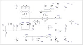
Here is current schematic.
I have added RC-filters to the supply rails. To increase PSRR.
I have changed the input RC-filter to 2.2k and 150pF
Added 2.2k base resistor in the VAS CCS.

I have added RC-filters to the supply rails. To increase PSRR.
I have changed the input RC-filter to 2.2k and 150pF
Added 2.2k base resistor in the VAS CCS.
I don't think it has anything to do with this, but the Q7 KSC3503 symbol is strange.Also, I tried using a TLV431 model, but could not get it to work at all (model sourced from Texas Instrument's site).
The plot below shows the effect of the BAV21J diode as Lineup has it connected. With gross overdrive and without the diode, the peak current flowing in the collector of U10 is ~450mA i.e. it will be destroyed. With the diode in place and with gross overdrive, the current is barely more than the standing current of the transistor - i.e. about 1.5mA.
Some of you may note that in my amps, I insert a 1k resistor in the beta helper transistor collector. I place this resistor very close to the device's collector and it's there to help dampen any tendency for HF parasitic oscillation. With this design, I do not think that is an issue though.
Red Trace = without BAV21J
Teal Trace - with BAV21J
You should do a loop gain plot to see what is going on here wrt PM and GM. C7 is normally used in VFA's like this to gain a little phase margin, but if you overcook it you end up with a pole above the ULGF that can add additional phase shift - i.e. it is actually counterproductive.
Separately, what is the frequency of oscillation? This may give a hint about what's going on.
Separately, what is the frequency of oscillation? This may give a hint about what's going on.
I agree with bonsai. C7 is a double-edged sword.
C7 is for canceling the input capacitance of U2 and must be selected so that C7/(input capacitance) = R8/R9.
If it is too large, ULGF will be postponed and it will become unstable.
Usually, it has a small capacitance of about 1p to 3pF.
I think it would be better to lower the impedance of R8, R9, and C1 further (e.g. 470Ω, 6.8kΩ, 220uF) to drive the extra pole formed by the input capacitance of U2 to higher frequencies.
Separately, what is the frequency of oscillation? This may give a hint about what's going on.
Well, now I can't get it to run at all. LT Spice complains that the timestep is too small. After playing with it a bit, I found that dropping the value of R7 gets the TRAN analysis to run (dropped to 2k). However, it doesn't resolve the DC point.
So... I switched from TI's model to OnSemi's model, and I get totally different results. Now, both CCS wont bias unless I set R7 to 10R or less. And even then it looks odd.
This makes me think the TLV431 models are not reliable for this purpose. So using a 1.24V voltage source is probably the best choice for a sim with LT Spice.
I would seriously recommend that the TLV431 be replaced with a red LED. They have a forward voltage drop of 1.8V and about the same dVbe vs temp as a transistor ie -2mV/K. This will at least give the current source 1st order cancellation of output current dependency upon temperature which it does not have now (it's about 50uA/K right now, so over a 30-degree temp change, expect the current source output to shift by 1.3mA). You won't have potential TLV431 stability issues to deal with either and it's cheaper!
Here's my take on this design. I changed the IPS and VAS CCS and tweaked the compensation. I changed all rail caps to 470u to make the physical layout easier. PSSR is still good at -86db at 100hz and -92db from 300hz to 20KHz.
Lineup's original schematic is built around 20V rails. Though with the components used, it should allow for higher voltages. Using Rod Elliott's P101 as a guide (this design is similar), it should be safe with up to 56V rails. I've sim'd at 20V and 56V and based on a quick review of the currents, it looks like it'll accept anywhere in the range without any component changes.
Phase and gain margin are 25db and 65 degrees with a ULGF of 1.1MHz
Slew rate is +20/-27 with 20V rails. With 56V rails, its symmetrical at 55 if C9 is added. This add positive feedback to mitigate negative slew rate limiting. Its to be determined if this creates instability in practice. I read about this in Douglas Self's book, though I don't recall seeing any designs that use it. Might be interesting to experiment with. Without C9, slew rate is +65/-40 with 56V rails.
THD is:
1k into 8R is 5 to 6 pmm from 1W to 15W.
20k into 8R is 46 pmm at 1W and rises to 255ppm at 15W.
With 56V rails, 1K THD remains at 6pmm up to 140W.
For the layout, I think Rod Elliott's P101 could be used for inspiration. It could probably be designed to fit flat against a Dissipante 2U heatsink. With their mounting brackets installed, the available space on the heatsink is 260mm x 54mm.
Attachments

@brian92fs Don't forget the current limiting base resistor for the VAS CCS bjt as originally brought up by wahab.
I assume R13 in your schematics is supposed to sit on the right-hand side.
I assume R13 in your schematics is supposed to sit on the right-hand side.
Well, now I can't get it to run at all. LT Spice complains that the timestep is too small. After playing with it a bit, I found that dropping the value of R7 gets the TRAN analysis to run (dropped to 2k). However, it doesn't resolve the DC point.
Such is simulation of more complex circuits. The active devices models that are available for free are not perfect. Sticking with the simulation is a so called armchair design. Simulation is a nice tool, but if you do not build the circuit, you know nothing.So... I switched from TI's model to OnSemi's model, and I get totally different results. Now, both CCS wont bias unless I set R7 to 10R or less. And even then it looks odd.
Yes. 1.24V across TLV431.Lineup - I tried to put this into LTspice but can't get the VAS to bias to the same level as your sims. The other LTSpice sims in this thread seem to show the same thing. We get around 5ma vs your 10ma.
Also, I tried using a TLV431 model, but could not get it to work at all (model sourced from Texas Instrument's site). So, I used a voltage source at 1.24V. Which I think is what your are trying to accomplish with the TLV431.
this is the model
Code:
.SUBCKT tlv431_new  6 7 11
*             A K FDBK
.MODEL DCLAMP D (IS=13.5N RS=25M N=1.59
+ CJO=45P VJ=.75 M=.302 TT=50.4N BV=36V IBV=1MA)
.MODEL DCL2 D RS=660K
V1 1 6 1.24
R1 6 2 15.6
C1 2 6 .5U
R2 2 3 100
C2 3 4 1.3U
R3 4 6 8
G2 6 8 3 6  .86
D1 5 8 DCLAMP
D2 7 8 DCLAMP
D4 6 8 DCLAMP
*V4 5 6 2
V4 5 6 1.2
G1 6 2 1 11 0.11
VCLAMP 9 6 14.5
D3  7 9 DCL2
* Add-ons
Rinp 11 6 8e6
Din1 11 7 DCLAMP
Din2 6 11 DCLAMP
DKA 6 7 DCLAMP
.ENDS- Home
- Amplifiers
- Solid State
- Cello One. Good Amplifier 15 Watt with TMC and Laterals