C5/C6 should be infinitely large, except that the output stage could never get down to operating bias - it could never finish charging up the caps. This is one of two limitations on the optimum size of these caps. The other is that bias, and therefore valve operating conditions, varies with an envelope of signal level. Even a pure Class A amplifier's average cathode current varies with signal level (even order distortion component harmonic # zero).
Adjustable/"fixed" bias circumvents this time constant at the expense of the DC stability of cathode bias. Or, you can keep operation fully within Class A, and like the original DTN Williamson, just not use a bypass cap. There's still a modulation of bias by signal level, but it has no time constant, and for triodes is reasonably small. Not your precis, but maybe interesting in the future. In pentode AB1, like you've proposed, output stages this would give a region of compression above the Class A region.
All good fortune,
Chris
It is cheaper and smaller size, as simple as that. If you look at other designs, for example Tubelab's SPP, it uses 1000uf. I tend to use 470u. EL84s typical cathode voltage in self bias for 330V UL is around -11V, therefore there is no reason to skim on the capacitor.Why use 220uF?
Yes, and once you've decided to bypass the cathode resistor, there's no reason not to have individual cathode resistors, each with its own bypass cap. Keeping the OPT's idling magnetic field near zero (balanced DC currents) minimizes its distortion contribution and to some extent, at lower frequencies, the output valves' contribution. For more detail, research the topic "B/H curves in iron core transformers", or something like that. Individual cathode resistors perform their DC feedback juju separately for each valve, and so better maintain DC balance in the OPT throughout the valves' working life.
All good fortune,
Chris
All good fortune,
Chris

I tend to use 470u.
there's no reason not to have individual cathode resistors
Thanks for the confirmation. I am going to look for physical space to use four individual resistors. If I can do it easily, I will. Because it's a PCB-based kit, I'll have to mount them off the board, on a terminal strip I guess. If I use four resistors and four caps, I get 320Ω per resistor instead of 160Ω, and 470uF seems like a better value for each of the four caps rather than 220uF, like this, right?
It seems like all amplifiers would use one resistor per tube, but my Dynaco ST-70 series ii does not, and neither does this amp. They both have 2 tubes on one resistor. It must not be a huge problem if tubes are matched properly in pairs. Then there is the "extreme" of the Dynaco ST-35, which only used one resistor for all four tubes. 😵 The ST-35 that I built has the add-on adjustable bias board.
It seems like this is a prime location for a top quality part. Recommended brands and series for the caps? Nichicon has so many series that I can't tell the difference. UKA series says "high grade audio equipment."
https://www.mouser.com/datasheet/2/293/e_uka-3082349.pdf
For the Faithful, the Curious & the Lurkers, how well do separate cathode resisters work to equalize cathode currents, all revealed here.
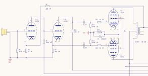
For this simulation I've used a circuit from NGO's previous thread, a PP EL84 driven by a common ECC85 driver circuit.
For the purpose of calculating standing currents, all reactive components may be ignored, they magically disappear at DC.
And pentodes are treated as triodes, at DC the OPT contributes only resistance. Plate current increases only slowly as plate voltage
is increased. But care must be taken for plate dissipation.
For the simulation I've used tube spec's found on the published data sheets. I've purposely set the emission of one of the EL34s 25% low.
When switch 'A' is closed the cathode resisters become a resistor of 150R common to both cathodes & the cathode currents are far apart.
Opening switch 'A' each EL84 has its own independent DC degeneration & the difference in cathode current drops to ~6%.
How Kool is that? Watch this space for the next exciting episode!👍
Attachments

More for those brave enough to be still here.😀
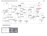
Sim one shews the condition when 1/4 volt is applied to the input grid with a weak tube in the output.
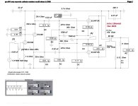
Sim two demonstrates what happens when just one cathode resistor is used.
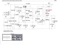
Sim three is what everyone would have, a perfect amp, all toobz in spec.
And of course it 'Sounds Great' , whatever that is.👍
Sim one shews the condition when 1/4 volt is applied to the input grid with a weak tube in the output.
Sim two demonstrates what happens when just one cathode resistor is used.
Sim three is what everyone would have, a perfect amp, all toobz in spec.
And of course it 'Sounds Great' , whatever that is.👍
Attachments
-
 EL84 PP w ECC85 Driver Amp Output as Weak Tube is Removed w Signal Applied_0003.jpg280.4 KB · Views: 121
 -
 EL84 PP w ECC85 Driver Amp Output as Weak Tube is Removed w Signal Applied_0002.jpg282.9 KB · Views: 135
 -
 EL84 PP w ECC85 Driver Amp Output as Weak Tube is Removed w Signal Applied_0001.jpg273.6 KB · Views: 130
Site was down for a while yesterday. Wonder what happened?
Why not use this tube matching approach mentioned earlier by @Kay Pirinha ? I had the amplifier apart last night, and I measured about 5mA difference on one channel and about 0.2mA on the other. I swapped one tube from each pair and both channels now measure about 0.5mA. Close enough to be a viable approach? Is it a real-world solution not requiring modification, even if it's not perfect? The tubes were originally matched on "current and Gm" per the seller, with whatever Russian tube tester he uses. The tubes now have a few hundred hours of use. My measurement was, of course, at idle, with the tubes warmed up.
I was interested in the cathode bypass capacitor size question. When I built the first amplifier, I used Nichicon UKA series 220uF caps. I have on hand some Nichicon UKA series 470uF, including a matched pair. I hate working on the amplifier since it's so cramped inside, but curiosity got the best of me. After 3 hours of tedious disassembly, fiddling, desoldering, resoldering, removing the flux from the PCB, and reassembling, I was relieved to find that the amplifier still works. It now has 470uF instead of 220uF caps. They are bypassed with 0.1 uF film caps since that happens to be what I had on hand.
Did going from 220uF to 470uF make an audible difference? I'm not sure. I'll spend a week listening to it before reaching any conclusion. If there is an audible difference, it will be slight. After a few hours I didn't hear any dramatic difference.
You don't even need to know the OT's primary DC resistance values. Instead, you'd put a current meter in the low milliamp range between both plates. Plate currents are balanced if the meter reads zero milliamps. This works well with a single pair of output tubes.
Best regards!
Why not use this tube matching approach mentioned earlier by @Kay Pirinha ? I had the amplifier apart last night, and I measured about 5mA difference on one channel and about 0.2mA on the other. I swapped one tube from each pair and both channels now measure about 0.5mA. Close enough to be a viable approach? Is it a real-world solution not requiring modification, even if it's not perfect? The tubes were originally matched on "current and Gm" per the seller, with whatever Russian tube tester he uses. The tubes now have a few hundred hours of use. My measurement was, of course, at idle, with the tubes warmed up.
I was interested in the cathode bypass capacitor size question. When I built the first amplifier, I used Nichicon UKA series 220uF caps. I have on hand some Nichicon UKA series 470uF, including a matched pair. I hate working on the amplifier since it's so cramped inside, but curiosity got the best of me. After 3 hours of tedious disassembly, fiddling, desoldering, resoldering, removing the flux from the PCB, and reassembling, I was relieved to find that the amplifier still works. It now has 470uF instead of 220uF caps. They are bypassed with 0.1 uF film caps since that happens to be what I had on hand.
Did going from 220uF to 470uF make an audible difference? I'm not sure. I'll spend a week listening to it before reaching any conclusion. If there is an audible difference, it will be slight. After a few hours I didn't hear any dramatic difference.
Last edited:
More on Russian to English tube letters and numbers:
I think everyone, including myself, may be confused about the lifespan rating of the 6П14П-EP (latin 6P14P-ER) tube. It is commonly cited as a 10,000 hour life tube, and this may be a mistake.
References:
I think everyone, including myself, may be confused about the lifespan rating of the 6П14П-EP (latin 6P14P-ER) tube. It is commonly cited as a 10,000 hour life tube, and this may be a mistake.
References:
- Russian spec sheet showing 5,000 hr life for the 6П14П-EP: https://rudatasheet.ru/tubes/6p14p/
- Rusian fifth position (after the dash) tube markings and meanings: https://priborazbor.ru/radiolampa-6p14p-er/
6П14П-EB on the tube = at least 5,000 hour life, increased mechanical strength and reliability
6П14П-EP on the tube = at least 5,000 hour life, P means increased radiation resistance
6П14П-EД on the tube ... would indicate especially high durability of 10,000 hours but as far as I know this tube does not exist - The Soviet-era Russian paper spec sheets that came with my 6П14П-EP tubes do not show a rated life. I ran OCR on them and then put them through several online translators. 🙁
Last edited:
Many of the Spec's you have refereed to are encountered only in stressful environments. Such as part of a comm or control system in a tank or aircraft.
That seems unlikely in this application, the information required is, how good is the vacuum & cathode materials.
A small leak can soon ruin cathode material. What is the long term outlook at some kind of reduced voltage & plate current?
I'm assuming you are not running these toobz at their limits. Or, maybe you will??🤔
A small leak can soon ruin cathode material.
These 6П14П-EP tubes have been shelved since they were manufactured in the 1980's. No major leaks sitting on the shelf for ~40 years I guess since they test fine. Pins are clean and not corroded so it looks like they weren't stored under very bad conditions. Four of them came with boxes and spec sheets. I would assume since they went through quality control, for military use, and have a rated lifespan, that they are not expected to leak to the point of being badly out of spec during use through that lifespan. Guitar guys love them and they have a reputation for standing up to guitar amp abuse.
In any case, 6П14П-EP sounds great in this amplifier. The 6П14П sounds ok, but not as good to my ears, maybe a little less clarity I'd say. The kit came with Chinese 6P14 tubes, but I blew up that quad before I had a chance to test them because I broke a winding on one OPT and had to fix that. With the new kit, I got a new quad of Chinese 6P14, so I'll be sure to try those. The problem with Chinese 6P14 tubes is quality control from what I read on Chinese discussion forums.
I have always taken the lifespan rating as a relative value, not absolute. The 6П14П is rated 3,000 hours. 6П14П-EB and 6П14П-EP apparently are both rated 5,000 hours. Under identical conditions (sitting in my stereo cabinet and not in an aircraft or tank) I would expect a little greater useful life from the latter. I do now suspect that the widely stated 10,000 hour life for 6П14П-EP is incorrect. It appears to be 5,000 hours.
Sovtek still makes the 6П14П-EB (Latin 6P14P-EV) at the same Reflektor factory and sells it as EL84M, so new production is available any time. I haven't had any issues with the NOS Soviet-era tubes, and they cost less, so I'm using those right now. I'll be interested to listen to the included Chinese 6P14. If they sound good, then I'll consider them a bonus that came with the kit.
how good is the vacuum & cathode materials.
I would assume that a greater lifespan rating would indicate higher quality materials and/or increased quality control on both points. The resistance to vibration, impact, and radiation would be mostly mechanical design I suppose.
I'm assuming you are not running these toobz at their limits. Or, maybe you will??🤔
The present amplifier is 337V anode, 10.3V bias with a 160Ohm cathode resistor shared between two tubes, if I use the calculator properly, I get 10W dissipation, and the tube is rated 14W. Someone earlier did note the overvoltage of 337V instead of 300V. It's not as bad as my ST-35 or some guitar amplifiers. The ST-35 is at 370V.
After some reading online, I have found that some guitar amps run the EL84 as high as 400V without longevity or sound quality problems, so long as the screen is kept at 300V or below, which is the case in this amplifier.
Also when dissipation is less than 100%, and it is 71.4% if I calculated correctly. Screen is regulated at 299V.
The question then becomes, how much "tube abuse" is too much? I'm not expecting exceptional tube life in the ST-35. It runs as hot as a fireplace. This little amp isn't so hard on the tubes. It actually doesn't even run very hot.
I have had a Dynaco ST-70 series ii since the early 1990's. I get about 2,000 hours out of a quad of EL34 tubes before they start to sound a little weak and I replace them.
Last edited:
Has anyone ever tried this trick? I forget where I found it:
Instead of a single cathode resistor to ground, use individual cathode resistors to ground. Connect the cathode bypass capacitors together and then ground them through a single resistor of around 14% of the value of the single cathode resistor. This will reduce IMD and 3rd harmonic.
It was attributed to Allen Wright from Vaccuum State using this schematic as an example: http://www.vacuumstate.com/

One problem I see in the schematic above vs. the description of the values to use is that I calculate a 32.9 Ohm resistor instead of 68 Ohm? If that amp used a single resistor, it would be 470/2 = 235 Ohm, correct? Then, 235*0.14 = 32.9 Ohm not 68 Ohm. Something doesn't add up. 🤔
Also, there must be a downside, or is the only downside the cost and complexity, which is not very much? Has anybody tried this trick?
Instead of a single cathode resistor to ground, use individual cathode resistors to ground. Connect the cathode bypass capacitors together and then ground them through a single resistor of around 14% of the value of the single cathode resistor. This will reduce IMD and 3rd harmonic.
It was attributed to Allen Wright from Vaccuum State using this schematic as an example: http://www.vacuumstate.com/
One problem I see in the schematic above vs. the description of the values to use is that I calculate a 32.9 Ohm resistor instead of 68 Ohm? If that amp used a single resistor, it would be 470/2 = 235 Ohm, correct? Then, 235*0.14 = 32.9 Ohm not 68 Ohm. Something doesn't add up. 🤔
Also, there must be a downside, or is the only downside the cost and complexity, which is not very much? Has anybody tried this trick?
Last edited:
In this case, the downside is you are trying to graft this & perhaps other mods to an existing pcb for questionable improvements.There must be a downside
Possible to damage the pcb & further you have no equipment save your ears to check results.
The downside doesn't look good. In general with toob amps we are all simply happy with a particular kind of distortion.
The loudspeaker(s) & the environment will be the final decision maker.
One way to reduce the 3rd harmonic in a PP pentode amplifier is to use a loadline that is steeper than the calcs would indicate for max power,
That would indicate an 8K P-P OPT where 10K P-P is calculated & so on. In a real application the loadline is never a straight line but an ellipse.
The lautsprecher is a reactive load. And much of the time it occupies a space of higher impedance. 🙂
The resistors would be mounted on a tab strip off to the side, not on the PCB. There is no room on the PCB. I think most people agree that it would be better to use one resistor per tube rather than one per channel if possible. If I am adding a tab strip to accomodate 4 resistors and 4 caps, 2 more resistors on the tab strip is no problem.
Correct. However, with a tab strip I could experiment fairly easily. No test equipment on hand though.
In the example above, 14% of 470 is 65.8, which explains the value of 68 Ohms. The question is, why 14%, and does this actually work? I can't find where it was posted. I copied it into my notes a while back.
& further you have no equipment save your ears to check results.
Correct. However, with a tab strip I could experiment fairly easily. No test equipment on hand though.
In the example above, 14% of 470 is 65.8, which explains the value of 68 Ohms. The question is, why 14%, and does this actually work? I can't find where it was posted. I copied it into my notes a while back.
Last edited:
Would be interesting to see the methodology used. Looking forward to that if you are able to find it. 👍In the example above, 14% of 470 is 65.8, which explains the value of 68 Ohms. The question is, why 14%, and does this actually work? I can't find where it was posted. I copied it into my notes a while back.
Yeah, it's hard to comment on these "special effects" because they tend to be level sensitive (depends on where and what you're measuring) and with some-better, some-less better, results, deeply depending on both signal level and one's definition of better.
All good fortune,
Chris
All good fortune,
Chris
This is why I ask first. If someone or several people say, "Yes that works and I have done it" then great. If not, I will avoid it. I looked around online and I can't find any additional information.
It does seem like using 4 individual resistors, one per tube, is recommended by most, but definitely not all. As usual, there are many examples where one resistor per pair of tubes, or shockingly even one for all four tubes, still results in amplifiers that people like. It should be fairly easy for me to put a tab strip off to the side for 4 resistors and 4 caps and run a jumper wire for each channel from the holes in the PCB. However, if I just end up using 1 per pair for whatever reason, as designed, I won't lose any sleep over it. 😴
It does seem like using 4 individual resistors, one per tube, is recommended by most, but definitely not all. As usual, there are many examples where one resistor per pair of tubes, or shockingly even one for all four tubes, still results in amplifiers that people like. It should be fairly easy for me to put a tab strip off to the side for 4 resistors and 4 caps and run a jumper wire for each channel from the holes in the PCB. However, if I just end up using 1 per pair for whatever reason, as designed, I won't lose any sleep over it. 😴
In general, you could say that the post #31 cathode arrangement is somewhere between an ordinary RC pair per output valve and the DTN Williamson no-cap original (the DTN Williamson has other ways of zeroing idling current imbalance), so will have an intermediate result. Ignoring the large-signal-important issue of bias time constants, the small signal case is that a common impedance between cathodes and signal ground provides a negative feedback whenever the valves might try to draw unequal currents, the result of even order distortions, so reduce those distortions (This actually includes DC, which is order zero, an even number). This has to be traded off against odd order effects, and the relative importance of these things varies significantly with signal level.
For experimental purposes, you could rig up a dual pot and see if it's audible in your particular circumstances. The danger is that you might decide that you can hear a best amount, but it would be different at different levels or something. Then you'd be on that proverbial canoe. Arf!
Al good fortune,
Chris
For bias, instead of two 160 Ohm 5 Watt resistors I should use four 320 Ohm 2 Watt resistors, correct? Each one is bypassed with a 220 or 470uF cap, correct?
If that is correct, I did a scale drawing, and I identified an area on the board (in red) where there are no traces on either side, so I can drill a mounting hole there with no harm. I can assemble what I will call a "bias module" off the board, using a 6-lug strip that I found at Mouser, and then mount it to the circuit board with a bolt and nut. There is plenty of room. Four short jumper wires would connect each tube to its resistor and capacitor. A short jumper connects all of the negatives to the ground point, which just happens to be right in the center.

Carefully cutting the PCB traces on the other side of the board (the top of the PCB where the tube sockets are) as shown below will sever the connection between pins #3 on each channel, leaving me able to connect each one independently using the jumpers shown above on the other side (the bottom) of the PCB.

It would end up looking something like this inside. The red, black, yellow, and green wires are the negative feedback connections to the PCB. They can be rerouted if needed. I would have to consider this a permanent installation as you can see how difficult it is to work inside this chassis. I was hoping that I could easily change the resistors and capacitors to experiment with different values, but having drawn it to scale, I now see that I should plan on getting it right the first time.

If that is correct, I did a scale drawing, and I identified an area on the board (in red) where there are no traces on either side, so I can drill a mounting hole there with no harm. I can assemble what I will call a "bias module" off the board, using a 6-lug strip that I found at Mouser, and then mount it to the circuit board with a bolt and nut. There is plenty of room. Four short jumper wires would connect each tube to its resistor and capacitor. A short jumper connects all of the negatives to the ground point, which just happens to be right in the center.
Carefully cutting the PCB traces on the other side of the board (the top of the PCB where the tube sockets are) as shown below will sever the connection between pins #3 on each channel, leaving me able to connect each one independently using the jumpers shown above on the other side (the bottom) of the PCB.
It would end up looking something like this inside. The red, black, yellow, and green wires are the negative feedback connections to the PCB. They can be rerouted if needed. I would have to consider this a permanent installation as you can see how difficult it is to work inside this chassis. I was hoping that I could easily change the resistors and capacitors to experiment with different values, but having drawn it to scale, I now see that I should plan on getting it right the first time.
Last edited:
Would be interesting to see the methodology used. Looking forward to that if you are able to find it. 👍
I finally found it!
I usually prefer fixed bias, but when I do cathode bias, I use Allen Wright Vacuumstate's trick with the cathodes:
![pp_1c_s[1].gif](https://www.diyaudio.com/community/attachments/pp_1c_s-1-gif.1043813/ "pp_1c_s[1].gif")
Use individual cathode resistors to ground, then connect the cathode bypass capacitors together and then ground through a single resistor of around 14% of the value of the single cathode resistor. This will reduce IMD and 3rd harmonic as well (there are some tests performed on this forum).
Good to see the schematic is still out there in the multiverse.
Is there some text with it describing the actual results & how the tests were done.
THX
Is there some text with it describing the actual results & how the tests were done.
THX
- Home
- Amplifiers
- Tubes / Valves
- Huaji Audio 6P14P (EL84) + 6N1P PP amp kit build #2