Mark Tillotson said:Well, very much depends on how you define the classes
My definition: a class B amplifier has a transfer characteristic whose slope becomes zero at one point, the origin.
Class B is unsuitable for audio because the slew rate required to straighten the transfer characteristic becomes infinite.
The OP's circuit is a hybrid that combines a class B amplifier with a class AB amplifier. It avoids the problem of zero slope and infinite slew rate at the cost of being two amplifiers. At this point, I would say just use class AB.
Ed
Class of operation is related to output devices. Here, in the post #1, there is no or negligible current through output devices until the opamp output reaches certain Vbe threshold. So, it cannot be class AB.
I wonder if a plot of the dynamic output impedance of both output devices against output voltage (assuming resistive load) would be illuminating?
H
HAYK

That is, maybe PMA doesn't see an improvement with 150 ohm because there is already more current flowing through the base-emitter capacitances than through that resistor when the circuit is going through the crossover region. I don't know, it's just a hypothesis.
Maybe this might help to understand?
Plots without 150R, including opamp output current

Plots with 150R

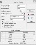
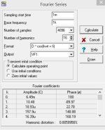
Comparison of THD vs. level at 10kHz, with and without 150R resistor

Loopgain stability analysis

Stability with 8R//capacitive load

Last edited:
Try this class B with your transistors. It saturates with -10v. Maybe another opamp is better.
Good, it stays simple, with minimum of parts. Gain is a bit low, though.
Do you have distortion analysis as well? At some higher frequency, like 5kHz or 10kHz. Not at 1kHz, at 1kHz it is uninteresting. Loopgain analysis?
H
HAYK
Looks good!


We can see class B behaviour in the THD/power plot. Transistors biased at 0.5V approx. Going higher to class AB, the negative slope of THD plot disappears and at low powers we have improvement in THD of several orders. At about 5W THD starts to be same.
We can see class B behaviour in the THD/power plot. Transistors biased at 0.5V approx. Going higher to class AB, the negative slope of THD plot disappears and at low powers we have improvement in THD of several orders. At about 5W THD starts to be same.
Last edited:
These are sim files for the current dumping' 741 amplifier. This fascinated me as a youngster.
I think it should click and run as everything is in the folder. The two voltage sources replace the diodes in the original and are the key to getting good performance by biasing the driver stage up to the point of conduction of the outputs.

I think it should click and run as everything is in the folder. The two voltage sources replace the diodes in the original and are the key to getting good performance by biasing the driver stage up to the point of conduction of the outputs.
Attachments
H
HAYK
BD139/140. Microcap 11 Professional. You are comparing apples and oranges. I tested at 10kHz and gain 23x and you can see it from attachments in my post #48. You are testing at gain 11x and 1kHz. Loopgain at 10kHz is of 20dB less than at 1kHz. You cannot take two different test conditions and make a comparison. It does not make any sense. Best to build the circuit, if you want to be serious. Simulator models precision is limited.I don't see what transistors you are using. I tested the same opamp with chosen bjt and got 0.0003% 1khz 11v 8ohm.
Last edited:
@HAYK
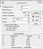
THD vs. power for circuit gain 11x, at 1kHz

Quite a difference compared to 10kHz THDlevel and gain 23x, right? We need to compare apples to apples, not apples to pears. Still, we can see inevitable underbiased class B issue.
And you definitely cannot get 11Vrms from +/-15V power supplies. 11Vrms makes 15.55Vpeak, +/-15.55Vp, which exceeds power supply range.
THD vs. power for circuit gain 11x, at 1kHz
Quite a difference compared to 10kHz THDlevel and gain 23x, right? We need to compare apples to apples, not apples to pears. Still, we can see inevitable underbiased class B issue.
And you definitely cannot get 11Vrms from +/-15V power supplies. 11Vrms makes 15.55Vpeak, +/-15.55Vp, which exceeds power supply range.
Last edited:
- Home
- Amplifiers
- Solid State
- Class B Circuit Opinions...