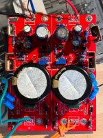
I have a problem, I have a PCM63 DAC, it requires bipolar power supply, when I connect both grounds, the positive Stub does not work stably. The light blinks.
When I remove the soil completely, everything works.
How to connect two lands?
When I remove the soil completely, everything works.
How to connect two lands?
The blue wire is the total ground, when I turn it off, everything works.
If you turn it on, it doesn't work.
The positive part of the board does not work, the light blinks and the sound is boom boom and that’s it.
What should I do?

If you turn it on, it doesn't work.
The positive part of the board does not work, the light blinks and the sound is boom boom and that’s it.
What should I do?
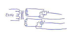
As I understand it, you need a dual polar transformer with a single common ground.
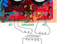
But to which “AC” do you need to connect the common wire from the transformer?
But to which “AC” do you need to connect the common wire from the transformer?
Attachments
Last edited:
No, you need a transformer with two completely separated secondary windings. A single center-tapped secondary winding will not do.
Your transformer's windings will connect directly to the bridge rectifiers. They will not connect to any ground.

Your transformer's windings will connect directly to the bridge rectifiers. They will not connect to any ground.
The best practice is to keep the grounds of the positive and negative regulators separated until you get to the load. There you can have the two grounds connect to each other.if there are two different windings... then where can I get a common ground?
What you have shown in the picture will not work. You need a transformer with two separate secondary windings and two full wave bridge rectifiers.
Nice construction!Salas I want to thank you for sharing this great regulator with us.
I made a small smd regulator pcb for my diy dac. The sound is absolutely fantastic. Better in every aspect than my current super regulator (which i maybe didn't tune very well i guess).
For now i feed it with smps wallwart, but I will buy suitable transformer soon.
19VDC smps input (will change to toroidal transformer 12VAC soon)
10,5VDC output
CCS setting-700mA
M1-IRF9610
M2-IRF530
BC859C and BC807-40 transistors
SUSUMU RG 0603 resistors 10-25ppm
2SK209-GR jfet-s for CCS-s (135R degeneration resistors, 1.8mA current)
Lite-On RED leds - will change that to HLMP-6000
C1-2x Nichicon 4700uF, 35V
C2-Nichicon ES 470uF, 35V
C3-SMD PANASONIC FC 100uF, 35V (0.15ohm ESR)
PCB is 4 layer of which 3 layers are GND. I wanted to have top and bottom layer separated by just 0.2mm
Out of 700mA CCS setting i have 500mA constant load (4 mini local shunts) 100-120mA spare current and the rest is used by digital portion
Is the ccs jfet suitable for my build? Is it not degrading the regulator performance?
View attachment 1243734View attachment 1243735View attachment 1243736
Did you design the DAC? Could you share the design?
Thanks!!!
I accidentally shorted the positive part. Has anyone encountered this problem? What usually burns out first?
The multimeter shows my set value. When I connect the load, the LED just blinks and that’s it. What could it be?
Replaced irf530, does not help
Replaced irf530, does not help
Last edited:
Try to replace the bjt in the ccs
Edit: though if you short the output of the regulator nothing should burn. The ccs will simply limit the short circuit current to its set current.
Edit: though if you short the output of the regulator nothing should burn. The ccs will simply limit the short circuit current to its set current.
I don’t really understand what it is, where is it located?
- Home
- Amplifiers
- Power Supplies
- Salas SSLV1.3 UltraBiB shunt regulator