You even say it nicely, lolwith mediocre baffle step compensation

The problem with big series inductance on the woofer for BSC is the phase offset at the xover between LF and HF. That screws up driver integration in the mids and moves the acoustic center on the midbass. The sensitivity also goes down with higher inductor DCR.
The fix would be to use a cored inductor in the LF LP, but that almost always hurts midrange purity on the midbass depending on quality of inductor chosen. I'd always steer clear of cored inductors in this position which increases the xover parts cost substantially running a heavy wire gauge.
Alternatives to combat excess baffle step series inductor would be a 2.5 way or 3 way, which makes things twice as large and way more expensive. In most cases you'll need a larger inductor on a smaller baffle anyways, so it may be all a moot point trying to get away from a 2 way design.
With rather small speakers (anything less than 12-15” wide) simple ‘big coil’ BSC generally takes too much sound power away just below where the baffle step kicks in. So your speaker can (will) sound thin. Now this doesn’t appear in every gated measurement well enough. It likely happens in the 500-700Hz range.
Bit late to the party but wanted to remind of Joachim's Arkadia series which used CA22s and U22s in different iterations, albeit ported. I think the XO can be found from searching German forums.You may want to look at the Seas U22 I mentioned earlier, mainly because its an easy woofer to work with in the mids, very efficient, mates well with your Alu dome SB tweeter
Another option which might work well sealed is the Monacor SPH-220HQ
I'm aware of the Arkadia, but I think Joachim just sells kits - doesn't publish crossovers.
The Monacor SPH-220HQ is indeed an option, F3 54Hz in 25 litres sealed. But it's the same price as the CA22RNX.
The Monacor SPH-220HQ is indeed an option, F3 54Hz in 25 litres sealed. But it's the same price as the CA22RNX.
and the U22REX is not a driver made for sealed, the Qms is so-so for mid purpose also. To woven polypro I'd rathergo for the SS woven fiber glass.
Was that meant for me? If so, is it confusion about the phase shift remark with large inductors for BSC?huh?
The reason alot of inductance used for BSC screws with xover transition is the resulting LP filter will have less than ideal FR and phase tracking behavior around the rolloff slopes. With a large inductor playing both rolls of BSC and part of the LP section, the other parts making up the filter will have altered component reactance (transient response). This is of course with filters steeper than 1st order since 2 inductors in series simply add together as a single larger one. Offset value filters can potentially cause overshoot, ringing and / or peaking FR.
You'll of course have to simulate all this if you want to combine BSC and LP sections with 2nd order or higher, but its a much less flexiible scenario when trying to only change the LP frequency by itself. You'll have to replace the big expensive BSC inductor to make any strategic changes. Separate BSC and LP makes everything more flexible in more ways than one.
I'm really picky trying to avoid creating fundamental xover design flaws which can be harder and more expensive to correct trying to integrate the BSC circuit with the LP. Its cheaper if you happen to get it dead on the first try, but more expensive if its not, usually leading to a compromise than the preferred result.
Hammering things into shape with DSP based EQ isn't necessarily the best sounding solution to a problem. A more ideal filter topology will sound, image and overall perform better with predictable driver integration using closer to ideal filters while keeping the BSC on its own. A separate large inductor with parallel bypass resistor aside from the LP filter is smarter IMO. This way you can move or alter the LP itself with minimal effort / cost and still have optimal BSC for the given baffle and driver combo. A zobel on the woofer helps too, but may be unnecessary if the driver doesn't have any major peaking in the upper mids.
Hopefully you understand where I'm coming from with this.
Its a very good sounding driver in the mids. Thats one of the reasons I recommended it.and the U22REX is not a driver made for sealed, the Qms is so-so for mid purpose also. To woven polypro I'd rathergo for the SS woven fiber glass.
No,Hopefully you understand where I'm coming from with this.
it's just a matter of changing the other filter components and/or changing the phase of the tweeter, until it fits.
After all those passive speakers I have made, this was never an issue from a phase/offset problem.
Or another way of saying it, is that you could connect the two just fine or no better/worse than with propper baffestep correction from a phase/offset perspective.
It's just like @markbakk said that it's very poor solution to tackle the bafflestep.
(especially the additional peak/hump you often get)
The cases that it works well are extremely rare.
Btw, with a DSP with IIR filters, you will have the exact same issue, since the phase change is the same as its analog equivalent using s-z plane mapping transforms.
Obviously you can add delays, but that is not the point here.
Interresting.With rather small speakers (anything less than 12-15” wide) simple ‘big coil’ BSC generally takes too much sound power away just below where the baffle step kicks in. So your speaker can (will) sound thin. Now this doesn’t appear in every gated measurement well enough. It likely happens in the 500-700Hz range.
Is the problem the inductance of the low pass filter serie coil ? Do you just talk about a 2 way only where a big serie coil (1.5 mH?) is padding down too much below the half baffle step transition (<500 hz for illustreation) ?
How would you rule the Bafle step around those 500 hz/700 hz, please ? I have a 26 cm width front baffle...
I dont have those issues with my designs because I measure 150 to 500 far field at listening position corrected for a stereo source with mono signal. We did it this way calibrating soffit mounted large format monitors. It was always dead on at maIn listening position and averaged for the majority of the desk width.I see crossovers with mediocre baffle step compensation all over the place. Big series coils that excessively reduce level below the baffle step. Calculate the impedance of a 2m2 coil plus 1m inductance of the voice coil at 500Hz and you know what I mean.
Sorry, I disagree. Baffle step needs to be optimized for the location where the speaker is placed (2 pi, 4 pi, etc) and for listening distance, including summed LF gain, not for anechoic or other unrealistic environments. I focus on smooth directivity so there are no abrupt changes in lower mid target response. Thats why I also use my ears to design a speaker and let the sims be an approximate starting point. The ear is the end recipient of the finished design and it needs to approve of the final product. I dont care about theoretical laboratory situations.No,
it's just a matter of changing the other filter components and/or changing the phase of the tweeter, until it fits.
After all those passive speakers I have made, this was never an issue from a phase/offset problem.
Or another way of saying it, is that you could connect the two just fine or no better/worse than with propper baffestep correction from a phase/offset perspective.
It's just like @markbakk said that it's very poor solution to tackle the bafflestep.
(especially the additional peak/hump you often get)
The cases that it works well are extremely rare.
Btw, with a DSP with IIR filters, you will have the exact same issue, since the phase change is the same as its analog equivalent using s-z plane mapping transforms.
Obviously you can add delays, but that is not the point here.
I don't build speakers for generic placement in various unknown or undefined environments. I build to suit my own tastes or those who want something to work in specific environments and like my designs. I use design methods which come across as unorthodox to people who believe you can only design a decent speaker if you follow a specific path of development using lots of measurement data. I can guarantee you my designs will sound as good as they can for the purpose they're designed and with all the limitations of parts used.
Yes, there are very scientific ways of theoretically doing things in the speaker building world. A few people on here will harp on doing things the "correct way" (ie their way), but there are other valid and effective ways of developing a well performing speaker design. I rely on my ears more than on test equipment. I'm sure you disapprove of this having any objective validity.
Measurements are guidelines for me and get me close to a workable performance level, but my ears do the refining. If it doesn't sound good, whats the point of it all? I'm blessed with accurate hearing and know response irregularities when I hear them. Most people dont have that amount of discernment ability with their ears. It takes alot of educating your hearing to get to that point and I have many arguments with people (like yourself), until I show them how well I can tell if something is wrong. Of course that will never happen over the internet hear, so you'll never know.
No, I still need measurement gear to deal with tricky situations, but not very often. Thats why I dont post butt loads of measurements other than some impedance curves, which are the most revealing data you can get on raw drivers aside from approximate THD measurements. If there are bumps and wiggles in the impedance curve of a direct radiating driver, you're usually dealing with a sub par piece. There's no fixing that sort of issue unless you want to compromise on the final design. I dont use drivers with audible resonance issues.
FIR and IIR filters behave differently and you can have linear phase DSP based filters. The problem with those is the artifacts you get with extreme corrections as well as pre ringing. Of course any form of EQ on any level will change phase as they're directly related. Thats basic knowledge.
I am experimenting right now with a SB Audience 8mw125. It's a experimental 3 way design with 8mw125 is working from 120hz to 3.5khz.
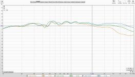
It will soon be limited to 120 - 800Hz range in a 4-way design with a dome midrange. Attached is a quick and dirty sweep in box in not so quite environment.
1st pic: in box sweep at 0,20,40deg.
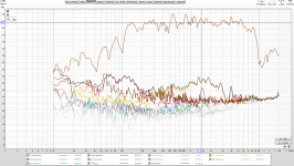
2nd pic: in box distortion. I don't know what my interface(quad capture), box or tda7297 is introducing in its own distortion to the mix. Especially the 3rd harmonic which is quite high. May be I need to do some loopback test. So take it for what it is.
Another worth noting is due its to natural roll off 8mw125 midrange is right now using only a single inductor(paralleled with a small cap) in its path.
And went further into experimenting with stereo recording and uploaded some video of same 3 way above. This was recorded at 8feet distance with ORTF cardioid mic. Recording came out hollow and smeared and also stereo separation is lost at that distance(best listened flat and disable any tilt/loudness eq). Sounds no where near what it sounds in person. But I will experiment more with distance/angle etc. Interesting days ahead.
But I guess you could notice what my little room treatment is doing to recording at 8feet distance.
Recording:
It will soon be limited to 120 - 800Hz range in a 4-way design with a dome midrange. Attached is a quick and dirty sweep in box in not so quite environment.
1st pic: in box sweep at 0,20,40deg.
2nd pic: in box distortion. I don't know what my interface(quad capture), box or tda7297 is introducing in its own distortion to the mix. Especially the 3rd harmonic which is quite high. May be I need to do some loopback test. So take it for what it is.
Another worth noting is due its to natural roll off 8mw125 midrange is right now using only a single inductor(paralleled with a small cap) in its path.
And went further into experimenting with stereo recording and uploaded some video of same 3 way above. This was recorded at 8feet distance with ORTF cardioid mic. Recording came out hollow and smeared and also stereo separation is lost at that distance(best listened flat and disable any tilt/loudness eq). Sounds no where near what it sounds in person. But I will experiment more with distance/angle etc. Interesting days ahead.
But I guess you could notice what my little room treatment is doing to recording at 8feet distance.
Recording:
Attachments
Last edited:
First, let me say @profiguy is right about considering the environment and placement of the speakers. So consider if you need a full BSC, e.g. speakers against (or in it certainly) the front wall might need none.How would you rule the Bafle step around those 500 hz/700 hz, please ? I have a 26 cm width front baffle...
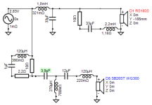
Second: there‘s info on this at various places, I believe even TG wrote about it. The general approach is to treat the BSC and the lowpass apart -in a way-. There are more options, but in the past I mostly used a tuned series LCR branch in parallel to the woofer. Like in the example added. This way you lose less voltage on the woofer (typically around 1-2dB higher system sensitivity), at the cost of lower impedance in the midrange. Nothing‘s perfect, but all my small (2-way) designs ended up with such circuitry, even back in the late ’80s and early ‘90s when I fooled around (anechoic room and old-fashioned Neutrik equipment at hand, we didn’t talk about BSC then, man, those were times 🤣).
Attachments
@markbakk Yes, the separate treatment of BSC makes the situation far easier to deal with in a few ways. That was my point in the last post. There are of course multiple ways to tackle the BSC, with or without integrating it into the LP.
I like the way you think. Your use of an LCR for BSC can be very advantageous and actually refine the correction curve more accurately to the specific speaker placement. The biggest complaint i usually have with more narrow baffled floor standers is they end up sounding "chesty" or congested in the lower mids when placed close to a wall but away from corners. The closer the LF driver is to the floor, the more sensitive the speaker is to placement.
Sometimes I integrate switchable lower mid EQ into passive networks with a multiple tap inductor I wound myself. This allows for alot of placement flexibility. You simply use a double deck rotary switch with one section for the inductor taps and the other for the capacitors. A second single deck rotary switch selects the amount of attenuation at the chosen center frequency.
- Home
- Loudspeakers
- Multi-Way
- Which 6.5" mid-bass for a sealed box?