Good idea to include gate stopper resistor options, even though they don't appear on the original ACA Mini.
Is the footprint for the H2 switch contacts, compatible with some sort of PCB-only jumper block? If someone builds two of these amp channels in the same chassis, it's possible they may not want to enable/disable H2 using a double pole switch, which likely requires two pairs of signal flywires (one wire-pair per channel) to that switch.
Is the footprint for the H2 switch contacts, compatible with some sort of PCB-only jumper block? If someone builds two of these amp channels in the same chassis, it's possible they may not want to enable/disable H2 using a double pole switch, which likely requires two pairs of signal flywires (one wire-pair per channel) to that switch.
Last edited:
Looking at the article and the use of the optional use of R11 C6 to correct the
inballence of the output devicesw made me wonder if this might also be used
in the F5 too.
inballence of the output devicesw made me wonder if this might also be used
in the F5 too.
What would the proper values be for gate stoppers? Thanks.Good idea to include gate stopper resistor options, even though they don't appear on the original ACA Mini.
You'll need a CRO (oscilloscope) for this exercise to really see the effect if any. Mr. Pass had his reasons not to include them and I guess they are good reasons.What would the proper values be for gate stoppers? Thanks.
I personally like gate/grid stoppers with mosfet/tube devices.
Start with 47 ohm and go up if necessary. I doubt if you'd need more than 220.
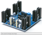
All of the Pass Labs preamplifier products are designed by Wayne Colburn. Including the Xs shown in #2446.
Thank you Nelson and all for sharing so generously, I have ordered a complete kit and am reading thru the posts. One thing that piqued my interest is the Mini Tower that 1 poster did with the ACA mini & ACP+. I was thinking it would be very cool to be able to make something like this w/ 2 inputs, what a cool integrated that would be?
I should add when I said "it would be cool to make..." I wasn't referring to me as I am a complete novice.
I should add when I said "it would be cool to make..." I wasn't referring to me as I am a complete novice.
D'Oh! Probably brain overload, just realized the ACP+ has provisions for 2 inputs 😳! Now I just need to figure out if I can piece it together or if they will be available complete thru the DIY store. Such a cool integrated amp!
If you want to make a combination of ACP+ and ACAmini, the logical place to start would be building both as normal, getting them adjusted and working properly (easy and straightforward) listening to them and falling totally in love with the sound (also easy) and then figuring out how to combine them in a form factor you find interesting. It’s DIY! Jump in, the water is fine.
🙂
🙂
I have 2 ACAMini kits on order, 1 might make a terrific gift. Acquiring the parts for the ACP+ might prove difficult with my level of knowledge, but thanks to the amazing people on this site and others I am slowly learning, very slowly at nearly 70 things don't stick all that well 😉
Just finished the ACA mini and need some help/suggestions. When I hook it up to my system I get nothing but dead silence. I measured the values of every resistor, double checked capacitor orientation and orientations of all transistors. Discovered and reoriented a one backward Q1 and one Q2. It adjusted properly: VO= 11.508 or so volts in each channel; VB adjusted to .303 volts in each channel. Pictures below. What should my next diagnostic steps be?


Thanks 6L6 for your reply. That was my suspicion as well-- something up stream from the ACA mini. I'm using a DAC as input from another system that works . The cables, etc. all from a known good system. This doesn't mean that I haven't done something wrong somewhere but I think I've tried the usual suspects. Maybe re-do it all again???
@getgoin: I assume your DAC has a variable output level and that you know it is above zero and not too high. Plus you need to be sure the source really is playing.
Ideally you'd test with another source through a preamp or amp with a preamp output.
Re the Mini: Are the heat sinks hot?
Good luck!
Ideally you'd test with another source through a preamp or amp with a preamp output.
Re the Mini: Are the heat sinks hot?
Good luck!
Mystery solved. I had two different DACs that both worked in other systems. Neither worked with the ACA mini. Tried a few more things and discovered that both my phone and tablet (tried both of them, too) had the volume turned all the way down. They feed a digital signal to the DAC. Turned it up and the ACA mini works like a charm. I'm playing it through horn based speakers and to me they sound noticeably honky compared to my previous amp. Would adjusting VO/VB make a difference on this front? I removed the jumpers and I think that may have helped but I'd have to A/B them some more to be sure.
Thanks you for your kind responses.
Thanks you for your kind responses.
- Home
- Amplifiers
- Pass Labs
- DIY ACA mini
