AFAIK there are no jumpers to set. Maybe it’s the wrong stationpi. Anyhoo, I’m done reading the manuals. If there are any secrets in there I’m not finding them.Since it works you know it's a jumper setting or controller setting or something. Are you using a controller? Do you have the jumpers set correctly for a controller or the output format you want if you aren't using a controller like monitor pi?
Take a step back, read the station pi and transport pi manual again after stepping back. This sounds redudent but I have found my issues many times after reading something the 4th time when I'm fresh and came back after being frustrated.
Put the reciver ddc where the pi would go and keep the pi seperate. This yes is buying more stuff but will work easier and you are going to reduce the Emi from the pi and end up winning overall.
Hello,Thanks guys,
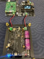
Zabloc,You are sure that the supercapacitor radiates inductance?So I will also put a separation between the supercapacitor and the Q7.
I remember asking Doede( dddac designer) about power supply chokes being close to HIS circuit. He told because it is a low impedance circuit the influence of a choke at close distance would be very small. Don't remember his exact words but this is pretty close.
When i first saw the picture i told myself finally someone who decides to reduce cable length between supercaps and consumer.
If the cap is spreading " garbage" why not cover the cap? If the caps are mounted in this " direction " radiation will be in the ok area and if current being consumed is low there won't be that much garbage or not?
Usually carefully designed circuit boards are not that sensitive they say. BUT what about all those wires with different functions all kind of randomly dumped into an enclosure or not even an enclosure creating aerials all over the place. I see them now every day in Ho chi min city.
Greetings,Eduard
P.s WHO told us digital audio is easy???
Attachments
Hi,
I posted on this thread a bit earlier and have now almost completed my DAC/Streamer project. I ran into one problem related to the LinearPi power:
The setup: Linearpi1 delivers +5VDC and the -5VDC is connected to the +5VDC of the LinearPi2. LinearPi2 delivers -5VDC and, together with LinearPi1 should create 0VDC.
Either LinearPi1 or 2 refuse to light up (power out LED) if the 0VDC cables are connected. Or: If I turn of one LinearPi the other lights up immediately.
Am I thinking something the wrong way? @iancanada is this some kind of electrical short protection?
Thanks for any help, an excellent community, here!
I posted on this thread a bit earlier and have now almost completed my DAC/Streamer project. I ran into one problem related to the LinearPi power:
- STATIONPI PRO as a board
- RP 4b
- FifoPi q7
- DUAL MONO MKII DAC ES9038Q2M
- OPA861
- 1x LinearPI (5VDC)for the dirty side and the screen.
- 1x LinearPi (5VDC) for the reclocker and the DAC
- 2x LinearPi (5VDC) for the OPA861
The setup: Linearpi1 delivers +5VDC and the -5VDC is connected to the +5VDC of the LinearPi2. LinearPi2 delivers -5VDC and, together with LinearPi1 should create 0VDC.
Either LinearPi1 or 2 refuse to light up (power out LED) if the 0VDC cables are connected. Or: If I turn of one LinearPi the other lights up immediately.
Am I thinking something the wrong way? @iancanada is this some kind of electrical short protection?
Thanks for any help, an excellent community, here!
The McFifo / XO clock is in the mail from Audiophonics and I'm trying to figure this out before it arrives.
Today it's, MCH / DAC:
MCK / MCK
BCLK / DCLK
LRCK / D1
data out 1&2 / D2
data out 3&4 / D3
data out 5&6 / D4
data out 7&8 / D5
@iancanada
Looking at your streamer buildup in post 10702. On what platform or basis did you built it?
Looking at your streamer buildup in post 10702. On what platform or basis did you built it?
Searching the article does not find the word 'radiate.' Moreover, inductance can't radiate. Magnetic flux might radiate, but not inductance....here is the link to the article...
So, what is it you guys read in the article that has you thinking there is a radiation problem?
Last edited:

Hello,
Of course there are also people who are not native English speakers so perhaps they will use the wrong word .
Déjà vu, most Americans cant even pronounce this in a way that a French man will understand it.
Greetings Eduard
Of course there are also people who are not native English speakers so perhaps they will use the wrong word .
Déjà vu, most Americans cant even pronounce this in a way that a French man will understand it.
Greetings Eduard
Understood. However, the question remains as to whether people should be adding shielding for some reason? If there is no reason, then I guess we should forget the whole thing.
Hello,
Of course it would be nicer if 95 % of the Canadian boards users only encounter minor issues but it seems like there are more than 5,% ending up in trouble.
Some things will be more important than others, as always, but " paying attention" to ten things that could be beneficial while not requiring a financial investment will in the end make you move forward. Maybe just autosuggestion but a lot of high end audio is all about illusion. If you see a pair of coke can caps the proces has already started . Let us just face it.
Greetings Eduard
Yes Edouard,I will also remove the Molex connector from the UcBalancer,So I could weld a cable of 16AWG in place,I have not found any information on the resistance value of the molex connector.When i first saw the picture i told myself finally someone who decides to reduce cable length between supercaps and consumer.
Markw,I had the same reaction as you.But that came from a good feeling from zabloc.So, what is it you guys read in the article that has you thinking there is a radiation problem?
🙂
Hello,
Usually it is not the wire but the connector that is the weakest point. If you check the inside of such a connector you will wonder why you invested this much in a small piece of cable. I think skipping some stages and just solder at least at one side directly at the copper track should be better. Usually a bare solid wire or a multi stranded wite with same diameter could already require a different method of connecting in order to be called a durable,/reliable connection.
Greetings Eduard
Yes, remove the male connector on the UcBalancer board,A solid cable through the hole properly weld will be judicious.
Hi Pete,Hey Ian,
I have a Station PI, it is powered by two LinearPi supplies, one each side. The Pi is a Pi5, the transport a TransportPI Digi (I think I have the last iteration). The Transport is connected to a DAC (I tried 2 different ones). I've tried both Coax and Optical. I get nothing.
The software is Volumio. I've selected Digi Berry Pro + (as stated in the manual) as I2S (I've also tried the Allo one)
Running USB directly from the Pi works fine. I don't know where to start looking. Any ideas ?
Thanks,
Pete
I have a good news for you.
Last night, I did a test myself with the same configuration and figured out the issue.
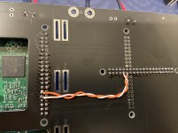
Reason: TransportPi Digi works in master clock mode which needs two additional hardware connections for the clock selection, but the StationPi doesn't provide such connections.
Solution: Solder two wires at back side of the StationPi PCB to connect both pin29 and pin31 between GPIO socket J1 and connector J7, please see the picture.
Result: Works like a charm no longer has any issue
Thank you so much for reporting the issue. Sorry for my late solution. Good luck to your project.
Ian
Attachments
Last edited:
I am also interested in help regarding this issue. Had identical symptoms when setting up LinearPi Duo for a symmetrical power supply. Then, after a few rounds of trying to get them to work properly and powering up and down, the position of the ON-OFF switches stopped making any difference. Both LinearPi are turned on permanently regardless of the ON-OFF switch position. Power out LED light on one LinearPi is permanently light up, the second one not, but both constantly provide correct voltages at their outputs.
Hi,
I posted on this thread a bit earlier and have now almost completed my DAC/Streamer project. I ran into one problem related to the LinearPi power:
My problem: Everything fires up nicely but the 2x5VDC for the OPA861 refuses to turn on.
- STATIONPI PRO as a board
- RP 4b
- FifoPi q7
- DUAL MONO MKII DAC ES9038Q2M
- OPA861
- 1x LinearPI (5VDC)for the dirty side and the screen.
- 1x LinearPi (5VDC) for the reclocker and the DAC
- 2x LinearPi (5VDC) for the OPA861
The setup: Linearpi1 delivers +5VDC and the -5VDC is connected to the +5VDC of the LinearPi2. LinearPi2 delivers -5VDC and, together with LinearPi1 should create 0VDC.
Either LinearPi1 or 2 refuse to light up (power out LED) if the 0VDC cables are connected. Or: If I turn of one LinearPi the other lights up immediately.
Am I thinking something the wrong way? @iancanada is this some kind of electrical short protection?
Thanks for any help, an excellent community, here!
So I have been going over this some more and as far as i2s connections go, I belive I got it right. Please correct me if I'm not, someone.
You can tell me if I'm right as well 🙂
Last edited:
From the McFifo manual I got this:
MCH streamer is also supposed to run as master so I belive this would be the way to do it.
One problem though, it might just as well have been in Latin 😕
-Master and slave controlled MCLK
McFIFO was set to master controlled MCLK mode by default. This is the normal operating mode of the McFIFO. In this mode, McFIFO will decide which XO is selected for MCLK according to input music.
However, McFIFO can also work with digital audio sources that have master clock mode. For example, USB streamer with two on board XOs. To implement this, we need to enable McFIFO’s slave controlled MCLK mode. In this mode,
Page 8 2017-6-15 iancanada.mail@gmail.com
XO selections will be controlled by digital audio source. SLAVE MCLK will be fed back to digital audio source from McFIFO as world master clock. Frequencies of SLAVE MCLK can be set by jumper settings. To do so, we need a couple of steps :
1. Enable slave controlled MCLK mode by driving SLEN pin on J8 to logic high.
SLEN=0 (OPEN without connection, default): master controlled MCLK mode
SLEN=1: slave controlled MCLK mode
2. Connect XO selection signal from digital audio source to XOSEL pin on J8.
XOSEL=0: XO1 is selected
XOSEL=1: XO2 is selected
(XOSEL pin can be left open if not in slave controlled mode by default)
3. Remove the two XOs from digital audio source. Connecting SLAVE MCLK from McFIFO to the finial output for that two XOs. J12 and J13 are equivalent (but with different driver), so either of them can be used for this purpose. U.fl coaxial cable is used to improve clock quality.
MCH streamer is also supposed to run as master so I belive this would be the way to do it.
One problem though, it might just as well have been in Latin 😕
- Home
- Source & Line
- Digital Line Level
- Asynchronous I2S FIFO project, an ultimate weapon to fight the jitter