Oh boy, these audiophiles, so anxious. Indeed 1.6mm pcb are just fine unless you want to go to Mars… great job Mark as always…
SB
SB
I collect components for the UDP3 in the moment (was lucky to get a PCB).
I have some TTC3710B / TTA1452B which are TO220 (hfe = 120 (min.), 80V).
I wonder if those could be used instead of TTC004B / TTA004B.
No problem to get a set of TTC004B/TTA004B.
It was just that the heatsink can take a TO220 device 🙂
I have some TTC3710B / TTA1452B which are TO220 (hfe = 120 (min.), 80V).
I wonder if those could be used instead of TTC004B / TTA004B.
No problem to get a set of TTC004B/TTA004B.
It was just that the heatsink can take a TO220 device 🙂
I have now almost got all components for the UDP3 PCB.
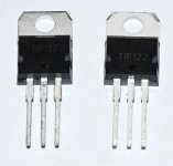
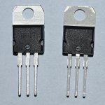
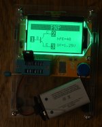
Regarding TIP122/127 I have looked at the major "stores" like DigiKey / RS / Mouser. None of these had the NPN / PNP is same brand (most have ST and Onsemi). As I like symmetry I ordered instead these transistors at a local store. Often I got some vintage components they have purchased many years ago. I was not 100% sure that both TIP122/127 was same brand but took the chance. I got same brand transistors and they tests well (Hfe 41 and 48) and tester recognizes them as PNP / NPN.
But what have I got? .....not much information on transistors. Only written TIP122 and TIP127 and then a very small logo showing "MJC". They look a little bit "cheap" but hopefully safe to use.
Attachments
For a Darlington the Hfe should be much higher but maybe the small cheap transistor tester have some limitations when measuring these.
The Parts List attached to post #1 of this thread, lists a second supplier for TIP122 and TIP127. See column "L" of the spreadsheet. I checked their website just now and they have stock of both parts.
I also checked the website of Futurlec, they have stock of both parts.
I also checked the website of Tayda Electronics, they have stock of both parts (mfr = ST Microelectronics).
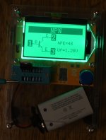
The Mega328 component tester seems to measure Darlington transistors incorrectly; it gets Vbe correct but Beta wrong.
_
I also checked the website of Futurlec, they have stock of both parts.
I also checked the website of Tayda Electronics, they have stock of both parts (mfr = ST Microelectronics).
The Mega328 component tester seems to measure Darlington transistors incorrectly; it gets Vbe correct but Beta wrong.
_
Attachments

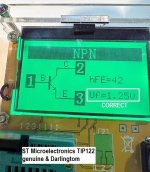
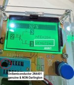

I think the internal base to emitter resistors cause the component testers to show low beta.
5K and 150 Ohms.
5K and 150 Ohms.
Here are my readings which I believe are true ST-devices. I also found a link to a ST datasheet at the web where I purchased these devices.
Also all the ST devices I found pictures off using google I could see the small circular MJC logo stamp. Probably a stamp from the China factory which made the transistors?
Also all the ST devices I found pictures off using google I could see the small circular MJC logo stamp. Probably a stamp from the China factory which made the transistors?
Attachments
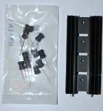
The 4 x heatsinks I got from DigiKey.
470 uH chokes from RS. These have a long and a short leg which I think indicates the winding direction.
Probably some applications where this is "nice to know"......the flux direction.
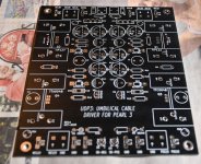
But I can see at the UDP3 PCB there is a square and round solder pad so even if is does not matter I will orient these chokes by using the square pad for the long leg 🙂
470 uH chokes from RS. These have a long and a short leg which I think indicates the winding direction.
Probably some applications where this is "nice to know"......the flux direction.
But I can see at the UDP3 PCB there is a square and round solder pad so even if is does not matter I will orient these chokes by using the square pad for the long leg 🙂
Attachments
Here is an extract of the technical data (of the choke mentionned in the BOM, don t know if same as yours/ brand and so on)
I don t think’ given this part and the schematic, that winding direction matters, but i would be happy to learn something

I don t think’ given this part and the schematic, that winding direction matters, but i would be happy to learn something
Yes, it is the Bourns.
In this data sheet revision they don't specify the "dot" that indicates start of winding (rev. 05/12).
https://docs.rs-online.com/5876/0900766b80fa59a3.pdf
It uses "long leg" instead of "dot" but spec. does not write what the "long leg" indicates......as far I can see.
In this data sheet revision they don't specify the "dot" that indicates start of winding (rev. 05/12).
https://docs.rs-online.com/5876/0900766b80fa59a3.pdf
It uses "long leg" instead of "dot" but spec. does not write what the "long leg" indicates......as far I can see.
You could consider inserting one of them in orientation-A and the other in orientation-B. If orientation makes no difference then this has no effect. If orientation does make a difference then you are guaranteed to be half-right and half-wrong. Which may be preferable to some builders.
The same heuristic can be applied to the ferrite beads and the fuses on UDP3, if you so desire.
If you're also building the SMD filters called "AmyAlice" you could repeat the heuristic on its feedthru capacitors as well.
The same heuristic can be applied to the ferrite beads and the fuses on UDP3, if you so desire.
If you're also building the SMD filters called "AmyAlice" you could repeat the heuristic on its feedthru capacitors as well.
It is just good to know that the implementation is 100% symmetrical 🙂 ....then I sleep better.
By the way.....the pcb fuses are "Swiss made"!
I also ordered 10nF and 1uF film capacitors for the filter just after the transformer. I had 22nF and 2.2uF that fits perfect but I thought better to be 100% compliant with schematic and sleep well. I will use a Toroidy 20VA transformer (2 x 22 VAC).
By the way.....the pcb fuses are "Swiss made"!
I also ordered 10nF and 1uF film capacitors for the filter just after the transformer. I had 22nF and 2.2uF that fits perfect but I thought better to be 100% compliant with schematic and sleep well. I will use a Toroidy 20VA transformer (2 x 22 VAC).
My board is up and running using a Talema trafo. Gives me around +/-19vdc with 15vac windings. Thank you Mark


Congratulations @manniraj ! That is a gorgeous build and your soldering + flux removal is best in class. Good on ya!
You are much more brave than me, I probably would have wrapped that IEC connector in three layers of blue masking tape before powering on. Same with the AC mains input connector on your transformer board. Timidity increases longevity (?).
Your build certainly did achieve "approximately 19 volts" on each rail, as predicted in post #1.
Last edited:
2 x 15VAC is below the design target range for UDP3. I'd recommend ordering a 2 x 22VAC transformer now, and installing quickly it when it arrives. Until then it is likely you can limp along with the existing 2x15 transformer, but your PSRR at 2xMainsFreq will probably be at least a factor of 100x (40dB) worse when supplying 120mA from POS19 and 120mA from NEG19 ... the expected draw from a pair of populated Pearl 3 boards. The troughs of the raw DC ripple waveform get worse and worse as you draw more and more load current, and those troughs will boot you in the gluteus.
"the raw DC ripple waveform" appears across capacitors C7 and C8 in the schematic of post #1.
"the raw DC ripple waveform" appears across capacitors C7 and C8 in the schematic of post #1.
- Home
- Amplifiers
- Pass Labs
- UDP3: Umbilical Cable Driver for Pearl 3 phonostage -- move Pearl 3 PSU into its own, distant, chassis