It looks the same but I can't tell what the colors are on mine because it's discolored. Am I reading the colors correctly on your photo as brown, brown, orange, which makes it 11K Ohm?
Thank you Handel for reference to the schematic page. I was able to verify the resistor is indeed 11K and 2W. You may want to consider replacing yours since this was apparently the source of failure. As mentioned earlier, I measured mine as 30 Ohms, a relative short, which would explain the burnt out part and slightly toasted circuit board. The resistor is connected to the LED which would explain what was done before. I noticed someone else had a picture of the soft start board where his resistor was replaced as well.
The LED resistor in my No 27 had previously cooked the board, and prior to me, was repaired by soldering two CC resistors in series. I removed them and used a higher value MO resistor and installed it elevated off the board.
Thanks. I have not had issues with that resistor but it was C316 or C319 which was broken and I had issues with the soft start because of that. Maybe worth of changing those when next time amp is open.
Anyone know where I can get the TO-220 lead extenders for mounting the TO-220 transistors to the PC board? It would be easier to replace them.
Mouser, Digikey, etc. Look for header pin sockets, 3 position, 1 row, IC & component sockets. Many to choose from. I had some in my own stock, so haven't had to order any, but it's a quick search on Mouser.
Hans,
I have a question about the balancing of the positive and negative output transistors.
When I am biasing the amp there is quite big difference between the positive and negative 10ohm base resistors of the output transistors. Is there way to match the current consumption so that both, positive and negative are approximately same? Or is that coming from the physical characteristics of the output teansistors?
I am currently repairing my No. 23, but I am in doubt as I cannot find two of these resistors in the schematic. I need help determining their exact values and locating them in the schematic.
.PNG")
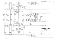

Thank you very much. I just realized that I can't find these details because I don't have the schematic. Therefore, I need to study more about testing to figure out how to determine the SAT resistor value. I can't take the measurement because the SAT resistor in the other section is burnt.The lower is the R69 and the upper is the SAT resistor(specified at test). I think the only way is to take the SAT resistor off and measure it to find the value. See attached voltage regulator schematic.
Actually I am exactly in the same phase. I am taking into use another board because the current board has so much wear and is not reliable anymore. Need to find good values for the SAT in order to have balanced regulator voltages...
Here is my progress: All of the capacitors I measured are within specifications, but I plan to replace them anyway. I will update here when I have more progress.

Handel;
Do you have more clearer picture of this section? I want to switch my No. 23 from 100V to 240V. Just want to make sure I've got it right and feel confident about the conversion. Thanks a bunch!

Do you have more clearer picture of this section? I want to switch my No. 23 from 100V to 240V. Just want to make sure I've got it right and feel confident about the conversion. Thanks a bunch!
You are right. The positive output transistors are tightly matched and so are the negative ones, but between pos and neg can be a large difference explaining the voltage differences over the 10R resistors.Hans,
I have a question about the balancing of the positive and negative output transistors.
When I am biasing the amp there is quite big difference between the positive and negative 10ohm base resistors of the output transistors. Is there way to match the current consumption so that both, positive and negative are approximately same? Or is that coming from the physical characteristics of the output teansistors?
Hans
- Home
- Amplifiers
- Solid State
- Mark Levinson No23 repair help