This sentence in your description does not make sense to me. "Q300 parallel to the relay will limit the voltage on the relay to 25 Volt with Zener D316." How is this possible if the DC supply voltage is only 20V?
You are confusing AC with DC.This sentence in your description does not make sense to me. "Q300 parallel to the relay will limit the voltage on the relay to 25 Volt with Zener D316." How is this possible if the DC supply voltage is only 20V?
Hans
O.k. You know better,The AC voltage is 20 so the DC across the 100uF filter cap should be about 19.
Succes,
Hans
Hans, I respect your knowledge and help. I would like to understand how 25V is possible across the relay.
AC 20V is 20Vrms or 28volt peak,
Substracting 1.2V for the rectifier leaves 26.8 on the 100uF.
Hans
Substracting 1.2V for the rectifier leaves 26.8 on the 100uF.
Hans
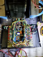
I tried powering the amp on today and the soft start relay still does not activate. Now I know why. There is only a small voltage across the 100uF DC filter cap instead of the 26 or so volts I should see. I never changed the wiring mess on this board and it made me suspect it may not be correct. I took a photo of what I have. Comparing it to the photo in post 15 the black jumper wires in the front are in a different place. In photo 15 the jumper goes from B to F. The other jumper looks unused with one end apparently pulled out. It seem to me D and E should be jumpered. Hans, can you help clarify here?
Attachments
The jumper position shown in post 15 is for 120V?
Can the amplifier turn on normally with both output modules disconnected?
With one module disconnected I am measuring a .6A current draw through a 75W light bulb.
The soft start relay is still not getting voltage.
Can the amplifier turn on normally with both output modules disconnected?
With one module disconnected I am measuring a .6A current draw through a 75W light bulb.
The soft start relay is still not getting voltage.
Can someone please help me make sense of the transformer primary winding arrangement? I am trying to verify my transformer is wired for 120V operation. Looking at the power supply schematic, which I assume is for 120V, I would expect that for the right channel OR-OR, BR-BR are wired together and in series with BL-BL, GR-GR since they are wound in the same direction. The schematic, however, shows OR-BR, BR-OR wired together in series with BL-GR, GR-BL.
No! In post 15, the company is based in Malaysia. It should be set for 230V or 240V. For 120V, it will be parallel in the primary.The jumper position shown in post 15 is for 120V?
Can the amplifier turn on normally with both output modules disconnected?
With one module disconnected I am measuring a .6A current draw through a 75W light bulb.
The soft start relay is still not getting voltage.
Something is completely out of whack now. Since I purchased the amplifier as a 120V unit I left the transformer primary wiring as is assuming it's correct and it agrees with the schematic. When I power the unit on through my current limiting light bulb I get a .6A draw but there is no sign of life. I measured the voltage across the two rectifier fuses on the power board and it measures .5V AC! If I disconnect the two transformer primaries at the fuse block and turn the unit on I get the expected 120V. Reconnecting each transformer and testing one at a time I get the same result as above with .5V AC across fuses and .6A draw. What could be common to both channels that would cause this. Both fuses on the rear are good and as an extra precaution I replaced them with 10A fast blows.
For 120V D should go to A and F to C.Can someone please help me make sense of the transformer primary winding arrangement? I am trying to verify my transformer is wired for 120V operation. Looking at the power supply schematic, which I assume is for 120V, I would expect that for the right channel OR-OR, BR-BR are wired together and in series with BL-BL, GR-GR since they are wound in the same direction. The schematic, however, shows OR-BR, BR-OR wired together in series with BL-GR, GR-BL.
Hans
Something is completely out of whack now. Since I purchased the amplifier as a 120V unit I left the transformer primary wiring as is assuming it's correct and it agrees with the schematic. When I power the unit on through my current limiting light bulb I get a .6A draw but there is no sign of life. I measured the voltage across the two rectifier fuses on the power board and it measures .5V AC! If I disconnect the two transformer primaries at the fuse block and turn the unit on I get the expected 120V. Reconnecting each transformer and testing one at a time I get the same result as above with .5V AC across fuses and .6A draw. What could be common to both channels that would cause this. Both fuses on the rear are good and as an extra precaution I replaced them with 10A fast blows.
The 120V mains is correctly entering on the fuses when they are removed, right?
What voltage drop do you measure over the light bulb when measuring 0.6Amp.
You could disconnect on the secondary side P363 and P369
When the bulb still draws 0.6Amp, put the the two back, try removing P384 and P354 and see what current flows through the bulb.
Hans
Thinking back over some experiments I did to try and solve the relay not activating issue I used an external power supply on the relay coil to activate it after turning the amp on so the 10 ohm power resistors do not overheat. My timing was off in one try where I activated the relay before turning on the amp. The room lights went dark for a second as the inrush current to the power supply capacitors sucked all the current. I didn't think much of it at the time but it seems the capacitors are probably shorted internally.
Disconnecting VCC at the diode bridge for both channels the bulb comes up dim with 40V across it. Both channels show 84V and the relay works. I ordered an LCR meter to check on the capacitor damage. It's a shame because the capacitors are new. At least the transformers seem OK.
Disconnecting VCC at the diode bridge for both channels the bulb comes up dim with 40V across it. Both channels show 84V and the relay works. I ordered an LCR meter to check on the capacitor damage. It's a shame because the capacitors are new. At least the transformers seem OK.
I have two shorted (collector to base) output transistors in the left channel, one MJ15024 and one 25. How closely do replacements need to match? Should they be matched for Hfe and Vbe?
- Home
- Amplifiers
- Solid State
- Mark Levinson No23 repair help