I am making some progress in trouble shooting. Using a 75W bulb in series with my 125V power, AC input power draw to the amp is 49.7V and .48A. The primary low voltage winding is 7.8V and the high 46.4. Voltage to the amp modules are:
Left Channel
VCC = 24.3V
-VCC = 24.3V
VCC Reg =33.5V
-VCC Reg =-33.5V
Right Channel
VCC = 24.5V
-VCC = 24.5V
VCC Reg =33.4V
-VCC Reg =-33.4V
Here is the odd part. On the left channel the .1 ohm bias resistor R44 has 23.8mV and R20 23.9mV. On the right channel both resistors measure 0V which I think is correct. Seems like the bias circuitry is being activated despite the low power voltage. What should I be checking next?
Ca. 24mV means 240mA, which seems a bit on the high side for these supply voltages, but no current could mean that the soft start circuitry doesn't release the end stage.
Try to get get higher voltages and measure again.
The VCC Reg's should be at least +/- 50 Volt because CR504 + CR517 prohibit the amp to function at lower voltages.
Also measure the LS output voltages.
Hans
Try to get get higher voltages and measure again.
The VCC Reg's should be at least +/- 50 Volt because CR504 + CR517 prohibit the amp to function at lower voltages.
Also measure the LS output voltages.
Hans

A couple of hours after writing my message the meaning of LS occurred to me, though I would have chosen LC. 🙂
Using two 75W bulbs AC input is 44V and .93A.
Left Channel
VCC = 24.3V
-VCC = 24.3V
VCC Reg =33.7V
-VCC Reg =-33.7V
LS = 9.7mV
R44 = 61mV
R20 = 61mV
Right Channel
VCC = 24.9V
-VCC = 24.9V
VCC Reg =33.8V
-VCC Reg =-33.8V
R44 = 0
R20 = 0
I am afraid to allow any more input power because I think the bias would rise tremendously which is probably what blew the two output transistors.
If you recall when powering the amp without the current limiting bulb the soft start relay bypassing the 10 ohm resistors would not activate. In later experiments with the output modules removed, I determined it does work when the primary voltage is present so it seems somehow the low voltage primary gets loaded with full input power to the amp.
Apart from putting a bulb into the AC line, it’s better to also insert current limiters into the +/- VCC lines. One end stage is drawing far too much current.
When more current is flowing as expected, it’s almost always the end stage itself causing this.
If this is also the case in your situation, you can remove the bulbs in the AC line and go on with current limiters in the VCC lines.
Hans
When more current is flowing as expected, it’s almost always the end stage itself causing this.
If this is also the case in your situation, you can remove the bulbs in the AC line and go on with current limiters in the VCC lines.
Hans
Would anything be damaged if I disconnected the collectors of Q40, Q30, Q29, Q52, Q41 and Q42? This would be an easy test to perform since I would only need to remove the heatsink attachment screws.
75 Watt would do.
Instead of removing collector screws it would be easier to remove the +/- wires from the two large rectifiers.
That will make the endstage powerless, but the voltage amps will still function.
Hans
Instead of removing collector screws it would be easier to remove the +/- wires from the two large rectifiers.
That will make the endstage powerless, but the voltage amps will still function.
Hans
I disconnected power from the left channel VCC bridge and powered up full power. The soft start relay clicked and the right channel functions fine. So the problem is in the end stage of the left channel. With my proposed screw removal the output transistors will be powered but the bias related ones would not so I could see where the problem lies. If you think this is safe I would try it.
I have not read all but before doing all this "semi-live" have you diod measured and to start with all the output transistors comparing to the good channel?
This is my data informed guess to the problem. I replaced seven of the output transistors. Since I could not find a closely matched MJ15024 I had to replace all of them. I have one good match '25 so just replaced the damaged one. When I turned the amp on using the bulb limiter I measured the emitter voltages on the '25s, and except for one which was a little higher than the rest (about .3mV), they seem balanced. That leaves the bias transistor (s) as the possible culprit.
Here they are
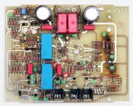
This is for a 23.5
But when you have a 23 these points are called WH.1 and WH.5
This is for a 23.5
But when you have a 23 these points are called WH.1 and WH.5
Attachments
Last edited:
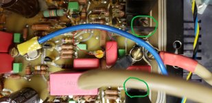
The 23 doesn't look quite the same but here are the two points I measured powering the amp through one 75W bulb.
value = 9.8mV

value = 9.8mV
Stop using the 75Watt bulb in the AC line, just have the two DC lines disconnected from the large rectifier, thereby interupting +/-VCC.
The Voltage amp should have it’s full VCC Reg of ca. +/- 85Volt.
Then measure between WH.1 and WH.5.
Hans
The Voltage amp should have it’s full VCC Reg of ca. +/- 85Volt.
Then measure between WH.1 and WH.5.
Hans
3.4 Volt is a bit on the high side with VCC disconnected, I would have expected 2.6 Volt.
But at least it shows that the Voltage Amp seems to be O.K. and so are Q38 and Q50.
Now measure in this same setup without +/-VCC the voltages over R45 and R50, resp 158R and 40.2R
Hans
But at least it shows that the Voltage Amp seems to be O.K. and so are Q38 and Q50.
Now measure in this same setup without +/-VCC the voltages over R45 and R50, resp 158R and 40.2R
Hans
- Home
- Amplifiers
- Solid State
- Mark Levinson No23 repair help