Let's clarify here. No one is saying that "significant" overshoot is the source of "pleasant" sound! Some builders, when tuning the feedback compensation, find that a slight overshoot at the leading edge is a valid approach. Dave Gillespie advocates for about 5% of the total waveform but no more than that.
To understand more about feedback and stability, I can't recommend this thread highly enough. It's a very good primer on the topic:
https://audiokarma.org/forums/index.php?threads/regilding-the-gilded-lily-heaths-w-2m.767851/
https://audiokarma.org/forums/index.php?threads/regilding-the-gilded-lily-heaths-w-2m.767851/
Okay I went into hyperfocus. Away with sleep haha.
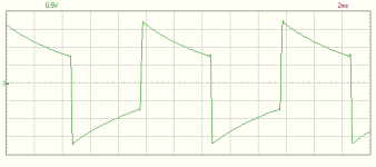
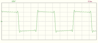
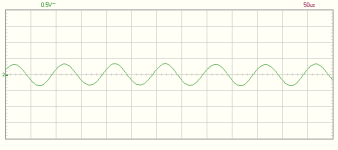
I have measured 100, 1000 and 10000 Hz with the resistive load. I think it looks as expected considering I should be unable to see a square at all at 10Khz. Notice there is some ringing. But as stated earlier this ringing is exactly the same as the ringing when measuring directly in the dac.
8594 is the 100Hz. 8595 is the 1Khz. 8596 is the 10Khz.
The amp was set in UL mode with NFB on while measuring.
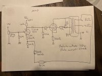
I also made a schematic which should give enough insight. It is. A schematic of the old school paper and pen type, but it should be readable. It is a single ended EL34 with Solid state rectification.
Please note: the amp has the option to take out the SS rectification and out a 5AR4 in it. For ease of drawing I left it out of the picture. I use the SS all the time anyway.
The amp also has a Triode / UL switch and switchable negative feedback going from the 8Ohm tap to the cathode of the 12ax7.
I have measured 100, 1000 and 10000 Hz with the resistive load. I think it looks as expected considering I should be unable to see a square at all at 10Khz. Notice there is some ringing. But as stated earlier this ringing is exactly the same as the ringing when measuring directly in the dac.
8594 is the 100Hz. 8595 is the 1Khz. 8596 is the 10Khz.
The amp was set in UL mode with NFB on while measuring.
I also made a schematic which should give enough insight. It is. A schematic of the old school paper and pen type, but it should be readable. It is a single ended EL34 with Solid state rectification.
Please note: the amp has the option to take out the SS rectification and out a 5AR4 in it. For ease of drawing I left it out of the picture. I use the SS all the time anyway.
The amp also has a Triode / UL switch and switchable negative feedback going from the 8Ohm tap to the cathode of the 12ax7.
Attachments

Last edited:
That’s way more exaggerated than the subtle coloration you get from a tube amp. That looks like someone ran it though an equalizer.wg_ski,
It is not amplifier overshoot, it is not amplifier instability.
I have measured many simple tube amplifiers that look like post #10.
They look essentially perfect on a load resistor, but just like that on a typical 2-way loudspeaker.
Especially amplifiers that do not have global negative feedback, and that have a low to moderate damping factor.
The intentional filtering is in the 2-way loudspeaker might be a simple 6dB/octave crossover at about 1200Hz, as a real good example.
Your Milage May have Varied.
Just my opinions and experience.
wg_ski,
There is a very good thread in Tubes/Valves: underdamped, over-damped, and critically damped woofer voltage waveforms.
It related the woofer and cabinet, versus the amplifier's damping factor.
jhstewart9 . . . was one of the major contributors . . . as I remember.
There is a very good thread in Tubes/Valves: underdamped, over-damped, and critically damped woofer voltage waveforms.
It related the woofer and cabinet, versus the amplifier's damping factor.
jhstewart9 . . . was one of the major contributors . . . as I remember.
Yarach,
Thanks for both of the schematics.
Why is there no bypass capacitor across the EL34 330 Ohm self bias resistor?
Could make things better.
Does your 10kHz square wave from the signal source look like a square wave, or does it look like the 10kHz sine wave from the amplifier output?
Where is the 30kHz 3rd harmonic of the square wave?
What is the model number, and manufacturers of your output transformer?
Is it rated for 67mA in the primary?
What is its rated primary impedance?

Thanks for all the detailed responses. I am quite amazed byu the level of questions being asked. There is really so much to learn!
I will try my best to answer.
Why is there no bypass capacitor across the EL34 330 Ohm self bias resistor?
To be honest: I like the sound better. I did extensive testing with bypass capacitors of around 470uF. I just notice the sound is less "accurate" and more fatiguing. It just does not resonate on my eardrums in the same way as it does without. Without the capcitor I get the tingling sensation in my ears in the same way I do when I play live with my band. This is especially noticeable with heavier rock types like Punk and Metal. With the capacitor in place the music becomes more mudded / compressed and instrument seperation is not the same as without the capacitor. With the bypass capacitor the sound is more fattened up and has more gain though. I figured this is since the bypass capacitor removes any local feedback.
The square waves look about the same with and without bypass capacitor. I believe there should be a difference as I can hear it, but my equipment is not advanced enough to measure it I guess.
I have read that using MKP capcitors as a bypass instead of electrolytic might fix that and give best of both wordls, but I did not go down that route yet.
The cathode resistor is of a non-inducive type.
Does your 10kHz square wave from the signal source look like a square wave, or does it look like the 10kHz sine wave from the amplifier output?
Please see the attached image. This one is taken directly from the DAC output.
As you notice the ringing pattern looks identical. So I dare to say the ringing as seen on the scope comes from the DAC.

Where is the 30kHz 3rd harmonic of the square wave?
I have no clue yet. I am new to amp design since last year. Scopes and harmonics is even newer to me. I know harmonics from music, but I have no idea how to recognize them on a scope yet.
What is the model number, and manufacturers of your output transformer?
Is it rated for 67mA in the primary?
What is its rated primary impedance?
I have a Toroidy OPT. It is reted for up to 100mA and the primary impedance is 3.2K Ohm.
https://sklep.toroidy.pl/en_US/p/TTG-EL34SE-Tube-output-UL-transformer-3,2kOhm-EL34-6L6-SE/560
I will try my best to answer.
Why is there no bypass capacitor across the EL34 330 Ohm self bias resistor?
To be honest: I like the sound better. I did extensive testing with bypass capacitors of around 470uF. I just notice the sound is less "accurate" and more fatiguing. It just does not resonate on my eardrums in the same way as it does without. Without the capcitor I get the tingling sensation in my ears in the same way I do when I play live with my band. This is especially noticeable with heavier rock types like Punk and Metal. With the capacitor in place the music becomes more mudded / compressed and instrument seperation is not the same as without the capacitor. With the bypass capacitor the sound is more fattened up and has more gain though. I figured this is since the bypass capacitor removes any local feedback.
The square waves look about the same with and without bypass capacitor. I believe there should be a difference as I can hear it, but my equipment is not advanced enough to measure it I guess.
I have read that using MKP capcitors as a bypass instead of electrolytic might fix that and give best of both wordls, but I did not go down that route yet.
The cathode resistor is of a non-inducive type.
Does your 10kHz square wave from the signal source look like a square wave, or does it look like the 10kHz sine wave from the amplifier output?
Please see the attached image. This one is taken directly from the DAC output.
As you notice the ringing pattern looks identical. So I dare to say the ringing as seen on the scope comes from the DAC.
Where is the 30kHz 3rd harmonic of the square wave?
I have no clue yet. I am new to amp design since last year. Scopes and harmonics is even newer to me. I know harmonics from music, but I have no idea how to recognize them on a scope yet.
What is the model number, and manufacturers of your output transformer?
Is it rated for 67mA in the primary?
What is its rated primary impedance?
I have a Toroidy OPT. It is reted for up to 100mA and the primary impedance is 3.2K Ohm.
https://sklep.toroidy.pl/en_US/p/TTG-EL34SE-Tube-output-UL-transformer-3,2kOhm-EL34-6L6-SE/560
Last edited:
I have never understood one of the specifications of the Toroidy output transformers, the large amount of the primary capacitance rating.
Your model's primary rating is 3.2k Ohms.
But its rated primary capacitance is 11.2nF.
The capacitive reactance, Xc = 1/(2 x pi x F x C)
Let F = 30kHz, and C = 11.2nF.
Xc = 474 Ohms at 30kHz.
30kHz is the 3rd harmonic of your 10kHz square wave.
474 Ohms of capacitive reactance is in parallel with 3.2k Ohms, to me, that seems like a severe low pass filter, so the 30kHz harmonic is very rolled off.
If you roll off all the harmonics of a 10kHz square wave, you get . . . a 10kHz sine wave, just like your screen shot.
Xc of 11.2nF = 3.2k Ohms at 4440 Hz, and the primary impedance is 3.2k Ohms. So the -3 dB frequency response is 4440 Hz.
Hello Toroidy Users . . .
Perhaps someone who has used that model of Toroidy can tell us how it performed at high frequencies, like 10kHz, 20kHZ, or 30kHz.
Last edited:
Good point!But its rated primary capacitance is 11.2nF.
Huge primary capacitance is the major drawback of toroidal OTs.
Reason is the close proximity of wire and conductive core.
I measured the capacitance of a few toroidals @ 100kHz and found values between 6nF and 30nF.
The specified bandwidth only seems possible when driven by a low impedance generator, which is kind of cheating.
Doesn't look like ringing. Looks like Gibbs Effect/Phenomenon. https://en.wikipedia.org/wiki/Gibbs_phenomenonI dare to say the ringing as seen on the scope comes from the DAC.
If it's the Gibbs effect it might be the result of missing higher harmonics because of the limited HF response of the amp.
Edit: I might be misinterpreting the Gibbs effect.
Edit: I might be misinterpreting the Gibbs effect.
Last edited:
Its produced by the digital filtering in the dac when you play a square wave. The time-domain waveshape can only be approximated with a limited band of frequencies (as viewed in the frequency domain)....this the result of using the DAC as a signal generator?
I understand, but wouldn't that only explain the slight waviness of the input signal and not why the amp increases it?Its produced by the digital filtering in the dac when you play a square wave. The time-domain waveshape can only be approximated with a limited band of frequencies (as viewed in the frequency domain).
Do you mean only the wiggles are bigger at the output of the amp? Or do you mean the whole waveform is bigger because its amplified?...why the amp increases it?
Guessing what you mean is the the wiggles look bigger at the output of the amp. If so, its probably because of the frequency response of the amplifier. The wiggles are at a high frequency (they have a short period), but the square wave itself has a longer period (its at a lower frequency).
Its produced by the digital filtering in the dac when you play a square wave. The time-domain waveshape can only be approximated with a limited band of frequencies (as viewed in the frequency domain).
So the DAC would be a poor source for test signals? OP would need a proper signal generator?
A dac can be okay for use as a signal generator. Its just that some dacs are not good for making square waves or other signals that need more bandwidth than the dac can reproduce.
Basically a DDS signal generator maybe more or less like this one is a type of dac: https://www.amazon.com/Professional...ocphy=9032419&hvtargid=pla-1950457148608&th=1 It can make square waves, but curved waves like sine waves will be approximated in a stair-step way.
Just depends on what measurements you want to do and what imperfections in test waveforms are okay or not okay for your purposes.
EDIT: Maybe helpful to study materials such as this: https://courses.washington.edu/phys431/scope_ex/scope_ex.pdf Then if you still want to learn more, maybe look up the reference documents listed at the end of this one. It will probably make more sense that way than asking questions like you are now. The problem now is that we are jumping around between different topics without laying a sufficient foundation in each area first.
Last edited:
Just for the occasion, here are the waveforms of my U-KT120 single-ended amplifier at 12.5WRMS / 10.00V output / 8R resistive load :
20Hz

200Hz

2kHz

20kHz

The measured bandwidth @12.5WRMS/8R/10.00V is :
15Hz-25kHz @-1dB
10Hz-45kHz @-3dB
The measured bandwidth @1.0WRMS/8R/2.83V is :
6Hz-25kHz @-1dB
4Hz-45kHz @-3dB
Oscilloscope : SIGLENT SDS-1202-XE
Signal Generator : SIGLENT SDG-810
The matching schematic :

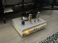
The build (one of the two mono blocks) :

And nonetheless, these amps do sound very fine too... 😉
T
20Hz
200Hz
2kHz
20kHz
The measured bandwidth @12.5WRMS/8R/10.00V is :
15Hz-25kHz @-1dB
10Hz-45kHz @-3dB
The measured bandwidth @1.0WRMS/8R/2.83V is :
6Hz-25kHz @-1dB
4Hz-45kHz @-3dB
Oscilloscope : SIGLENT SDS-1202-XE
Signal Generator : SIGLENT SDG-810
The matching schematic :
The build (one of the two mono blocks) :
And nonetheless, these amps do sound very fine too... 😉
T
That looks just like one would expect. Monotonic (not curved) tilt at low frequency, still pretty square at 2k, and rounding at 20 KHz. A little too much ring on the square wave at 2k, one would hope it died out sooner - at least there is no leading edge spike. But you may or may not be able to get to lower (I wouldn’t know till I tried). Unless it’s sampling error from a digital source in that case not generated by the amp anyway.
- Home
- Amplifiers
- Tubes / Valves
- Riddle me this...