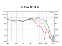
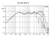
if the revel clone has an already done xover, I'd just get the stock tweeters for the build and not drive myself crazy trying to make a new xover.
@chargedcapacitor I guess I just don't know enough to say one is better than the other. I was sort of following the build progression. The builder said...something about the SB was "bothering" him...and he couldn't ignore it and decided to try the Scanspeak. being new... I trusted him (seemed to know what he was doing).
I just took some measurements of the same driver in the second enclosure (same design), and then I tried the second driver. Traces look very similar (both have that same drop in the 250-300hz range. I will upload a picture of the traces shortly (raw without any adjustments).

I just took some measurements of the same driver in the second enclosure (same design), and then I tried the second driver. Traces look very similar (both have that same drop in the 250-300hz range. I will upload a picture of the traces shortly (raw without any adjustments).
I thought it would be "fun" to try to incorporate the Morel speakers.... (especially since I already own them).if the revel clone has an already done xover, I'd just get the stock tweeters for the build and not drive myself crazy trying to make a new xover.
The SB15 alum version does have significant breakup resonance (which the builder was likely referring to, if they did not do properly control for it); it is something you run into if you cross it too high or put in too low of an order crossover. Either way, a simple series or parallel notch filter can take care of that. Personally, I think it should have a notch filter regardless.@chargedcapacitor I guess I just don't know enough to say one is better than the other. I was sort of following the build progression. The builder said...something about the SB was "bothering" him...and he couldn't ignore it and decided to try the Scanspeak. being new... I trusted him (seemed to know what he was doing).
I just took some measurements of the same driver in the second enclosure (same design), and then I tried the second driver. Traces look very similar (both have that same drop in the 250-300hz range. I will upload a picture of the traces shortly (raw without any adjustments).View attachment 1231391
I still think your measurements are off. Could you post a graph of the impulse response? And a pic of your microphone setup?
Jopldangla, phase in the simulations is difficult to see as you are showing it. I'd look to unwrap it.
This is generally my microphone setup for near field. Far field is the same… just a few feet back. (this is a mockup btw. real testing was done without anything on or around the speaker, other the the speaker stand and the microphone stand. The computer, amp and such were all behind the enclosure.


Last edited:
Here is the impulse response. I moved the window way to the right so you can see the full impulse response. The first response was taken at 0deg, outside today(green color). The second picture (orange color) was taken the other day in the warehouse I mentioned previously. The third picture (purple) was near field taken in the warehouse the other day. They do look different from one to the other, maybe I switched the pos/neg wiring from one day to the next.


Last edited:
@shadowplay62 Thank you for doing all of that. I looked into the impedance measurements using REW, but I don't believe I can accomplish that since I don't have a sound card with multiple outputs. I may just have to use the trace from the datasheet to at least get me somewhat close.
The baffle of this enclosure is 8.25" wide (width of the box, although the box has 1.25" radius on each side of the baffle) and the height is 12.875"
The reason the TW doesn't have data below 1000hz is I only swept from 1000hz and up (I was worried about damaging the tweeter with a sweep starting too low). For the woofer, I stopped the frequency sweep at 6khz. do you think I need to sweep the tweeter starting at a lower frequency?
You can go lower with the tweeter, I usually start at 500hz. You should go full range with the woofer.
@wafflesomd ... by full range you mean up to 20khz? since I am crossing under 3khz, do I need to rerun full range?
Doing full range woofer measurement will only give you more data to help in xover design, there's no downside. Cutting it short however can negatively impact what you have to work with to make filters. Many woofers have break up fairly high up that needs to be in the measurements.
You are welcome.
Waffleomd already answered you about the measurement range of the drivers. For impedance measurement you do not need any special soundcard. Search "arta jig" or "impedance measurement jig" in the forum.
Do not use the impedance curve as it is measured in free air. If you cannot measure the impedance of the wf in your box it's better to use the ones simulated in the Enclosure tool. The zip file contains the diffraction and the impedance/spl (NF) responses.
Attachments
Thx. Your impulse response isn’t clean. After 2ms there is something odd and it’s there in all measurements. Since your level sweeps are far from flat, it’s worth trying to get rid of it. 2ms equals about 2ft extra path length. It’s a pretty broadband signal, it seems to start just above 100Hz and maxes out in the midrange. Also the microphone clip you use, will reflect and cause non-ruler flat measurements at high frequencie.
Thanks Lojzek for clarifying that.
Interesting, it just looked weird to me, especially the amount of change in that frequency area.
Interesting, it just looked weird to me, especially the amount of change in that frequency area.
This is the measurement stand I placed this on top of a filing cabinet.
Your stand looks just short of 68.8 cm (2 ms), judging from cabinet height (32 cm according to ASR). My guess is that you either placed something just in front of the filing cabinet, thinking it being in its shadow wouldn't affect the measurement, or it is the filing cabinet itself, if I underestimated the height of the stand due to perspective.
In any case, your measurements include a strong reflection of an object that should be easily identifiable.
@sheeple @markbakk I did some additional investigating tonight.
I have done the following:
1. Raised speaker higher off the ground. (around 4.5' now)
2. Tried a different mic stand
3. Held the mic in my hand
4. Drove the tweeter instead of the woofer.
5. intentionally placed some random item in front of the speaker stand and it extended from the ground to approx 3' up.
6. Tried a different docking station hub (connected mic and HDMI to it)
7. Connected microphone directly to computer and sound through docking station HDMI
8. (haven't tried this yet) different computer.
In the above case, the speaker is sitting on a stand which is effectively a straight baffle. The nearest item in front of the speaker is approx 10' away (other than the microphone).
In all of these cases I am seeing something in the impulse at 2.5ms and 4ms. (blue is tweeter, orange is woofer). How worried should I be with these blips?
You must exclude all reflections, and a gate of 2.5 ms is not good enough.How worried should I be with these blips?
Why would you do that?5. intentionally placed some random item in front of the speaker stand and it extended from the ground to approx 3' up.
- Home
- Loudspeakers
- Multi-Way
- DIY 2-Way - looking for some guidance

