@augerpro Here is the .step file for the crappy waveguide I worked up. The good news is that the 3 studs, and center diameter, as well as the sealing surface on the rear of it seems to be working great. I will follow this up with pictures and measurements of the morel st1108 tweeter.
Attachments

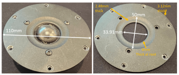
@augerpro here are the detailed dimensions. If you look at the step file you will see the 3 mounting hole pattern is at a weird angle, this was to allow better access of the terminals.
The foam on the face is flush with the surface where the faceplate bottoms out against, which I found odd (maybe it is flush because it has been compressed for a while already). On the step file you will see a raised surface to provide a better sealing surface (that was my hope). I provided measurements of the tweeter and faceplate, maybe they will offer some insight? Note that the faceplate curved surface essentially terminates to the underside of the plate (meaning it is a constant radius and has 0mm thickness at this ID of the faceplate location).
All measurements were taken with my calipers. I am happy to convert to inches, if that is what you prefer.
edit: fixed thickness dimension on second picture. was 2.48mm thk, now 1.54mm thk.
Attachments
Last edited:
The directivity of the woofer looks odd to me. You might want to have a read of this and the surrounding posts for a discussion of merging in Vituix.Here is my six-pack and crossover design. Any suggestions?
https://www.diyaudio.com/community/threads/a-3-way-design-study.376620/post-7142256
Making waveguides for dome tweeters can be a tricky business. You either need quite accurate measurements to allow for simulation (much more reliable with hard domes) or often quite a lot of trial and error. It is really hard to take someone else's work and "modify" it successfully in one go. Somehow you have created a situation where radiation from different parts of the dome and surround are interfering with each other badly.
That doesn't look too bad but there is still some variation at the lowest frequencies where I would expect them to fully converge at some point. Rear ported designs do produce negative directivity at low frequencies which can skew the graphs somewhat. Do you have simulated baffle diffraction loss in the merge?@fluid I believe I did the merging correctly. (assuming you were trying to point out the force gradient feature in Vituix).
This is the directivity of only the woofer with crossover filtering disable.
This image from Vineeth shows what I would expect. All the curves in the Power and DI graph converge at the point where the radiation is completely omnipolar.
If you normalize the horizontal directivity in Vituix it will be easier to compare. In your graph from #74 the DI is only a couple of dB by 1K. This is like an infinite baffle response not what I would expect from a woofer in a a box.
If you look at McFly/Mainframe's measurements of the Scanspeak they make sense. Negative directivity from the rear port rising directivity from the woofer in the box. Power and DI curves all converging.
@fluid i used the Bagby excel sheet to generate the baffle diffraction loss based on my driver position and baffle size. I then followed the “quasi-anechoic “ write up on ASR to combine.. ultimately combining with the far field (I used the equation to calculate spl correction between port and near field woofer)
I am now noticing that most folks directivity graphs are from -180 to +180. mine only go from -90 to +90. am i supposed to be spinning the woofer past the 90deg from normal? or.. what am i doing wrong.
i will check the other graphs you shared when i get in front of a computer. my phone screen is too small to make out the differences.
I would personally do the diffraction simulation in Vituix. As you are using REW I would follow the REW measurement guide from Kimmo, there is an example in there to follow. It is not to say that there is anything wrong with Bagby's spreadsheet or the ASR quasi anechoic tutorial, but Vituix works all in one.
https://kimmosaunisto.net/Software/VituixCAD/VituixCAD_Measurement_REW.pdf
Only measuring to 90 degrees is not as accurate as going all the way round to 180 if you are looking to better characterize the free field radiation. The data beyond 90 degrees can often be tricky to get right with limited gate time and nearby obstructions. Vituix can interpolate but the better data you feed it the less it has to guess.
There really are so many little things that can go wrong trying to measure speakers. It is good for anyone starting out to try and measure a speaker that someone reliable has also measured, so you can use it as a benchmark to see if you are doing things correctly.
Edit: On a more positive note, getting slightly off looking low frequency measurements won't stop your speaker from sounding OK if you did everything else well 🙂
I tried one of the new waveguide today, and I also tried the tweeters in their original mounting plate. Is it common for two "matched pair" speakers to be off 2-3db in SPL? To my amateur eye the Waveguide seems to be flattening that issue at 6500hz, and so it is seems to be helping? I will be trying the second waveguide tomorrow.
Red: Speaker 1 - 1 : 0.68 Waveguide Mounted
Green: Speaker 2 - 1 : 0.68 Waveguide Mounted
Blurple: Speaker 1 - Standard Mounting Plate
Orange: Speaker 2 - Standard Mounting Plate
In all tests the volume on the amplifier was unchanged, the microphone was unmoved, and the tweeter was centered on the microphone.
Bummer. I kinda thought that might happen with the .68 elliptical. I've only had a couple soft domes work well on elliptical waveguides. The .82 should be better, that's why I included it.
Yeah. The original responses don’t look so hot. I didn’t test these in the ideal location, but by comparison the WG is better. I am thinking it may be time to move on from the Morels in favor of the SB acoustics… as the revel copy was designed.
Given the low cost of the SB26 drivers and their relatively high performance that is a very good idea 🙂I am thinking it may be time to move on from the Morels in favor of the SB acoustics… as the revel copy was designed.
You'd be amazed at what even those cheap SB26ST tweeters can do. One step up to the metal SB26ADC and you are on almost stellar level, whatever all Revelator/Illuminator/Bliesma/Satori/Excel lovers might say to that.
Here is the updated Tweeter. I think its time to switch to the SBAcoustics... thanks everyone. Once I get the SBAcoustics I will come back.

change of plans. I am going to finish this speaker with the .68 waveguide and take some measurements of the 2-way with crossover. If it sucks I will replace the Morels and update the x-over. Wish me luck. 😀
- Home
- Loudspeakers
- Multi-Way
- DIY 2-Way - looking for some guidance