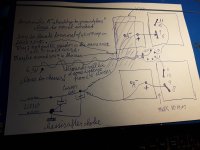
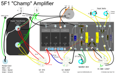
Thanks for all the help today everyone. I have modified I think per feedback. I always seem to get mistakes in. The software like to move the little connectors around. I am not sure about cap polarity for the C3/4 230ufs. I have changed the RC legs back to 600 (R8 and R9). Left in red as they may need to be adjusted. Still not sure about where and when earth goes to chasis. I think i have followed advice but I am now tired. The software tells me Im going to blow something up when joining earth to chasis grounds 😎 I have added XLRs for the first time as the ISO/Tango NP-126 (L3 and L4) are going to convert to XLR. I need to find transformer icons with the right connectors, so this will have to do for now. I've mirrored everything starting after C2....so it should be easier to read and find mistakes too!
Maybe it's getting closer to final dev version to start building.

Maybe it's getting closer to final dev version to start building.
@Thekak here is the second “choke” L2 cossor. From what I have read it is acting as both and inductor to slow down current flow going in and back on the 60 cycles and smoothing out those transients.
The value I measure across is about 115ohms close to what is labeled.
So when you say ” change the resistance value” you mean add series resistance if required?
The value I measure across is about 115ohms close to what is labeled.
So when you say ” change the resistance value” you mean add series resistance if required?
Attachments


Eduard, what's bothering you? Do you think you are being ignored? Are we being foolish? I have enjoyed reading your posts and you've given great advice and corrections.
Yes, I mean you can add a resistor in series with the choke.
Yes, I mean you can add a resistor in series with the choke.
I can't
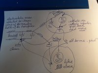
You are using an earth and a ground symbol in three locations. You should earth at one point. You can ground to chassis at multiple points if you want to try that some people do not endorse that approach. I know it's common with guitar amplifiers. There's a huge number of discussions about grounding in this forum and elsewhere, including the Valve Wizard site. I really like the grounding scheme that Eduard is suggesting and have had success with it. I would follow that.
Do you have a variac? If not, you might consider setting up a safety light bulb when you start making connections. I know you've had experience before but just throwing that out there.
I can't comment on XLR -> OPT connections or XLR "grounding" since I have no experience with that. But you need to be connected C2 (-) terminal to C1 (-) terminal in your schematic. C3 and C4 would return to C2.Thanks for all the help today everyone. I have modified I think per feedback. I always seem to get mistakes in. The software like to move the little connectors around. I am not sure about cap polarity for the C3/4 230ufs. I have changed the RC legs back to 600 (R8 and R9). Left in red as they may need to be adjusted. Still not sure about where and when earth goes to chasis. I think i have followed advice but I am now tired. The software tells me Im going to blow something up when joining earth to chasis grounds 😎 I have added XLRs for the first time as the ISO/Tango NP-126 (L3 and L4) are going to convert to XLR. I need to find transformer icons with the right connectors, so this will have to do for now. I've mirrored everything starting after C2....so it should be easier to read and find mistakes too!
Maybe it's getting closer to final dev version to start building.
View attachment 1230989
You are using an earth and a ground symbol in three locations. You should earth at one point. You can ground to chassis at multiple points if you want to try that some people do not endorse that approach. I know it's common with guitar amplifiers. There's a huge number of discussions about grounding in this forum and elsewhere, including the Valve Wizard site. I really like the grounding scheme that Eduard is suggesting and have had success with it. I would follow that.
Do you have a variac? If not, you might consider setting up a safety light bulb when you start making connections. I know you've had experience before but just throwing that out there.
Ha Ha. I guess nobody thinks I can build this thing!
The original circuit must be a pile of 💩 I guess....
Let's not talk about the 14 earth points on it....at least i've reduced it to 3.....
and fixed a B+ 265VDC rail represented as an "earth ground".
The original circuit must be a pile of 💩 I guess....
Let's not talk about the 14 earth points on it....at least i've reduced it to 3.....
and fixed a B+ 265VDC rail represented as an "earth ground".
Attachments
complete tube newbie. need all the safety advice I can get. was thinking of getting a variac....will the lightbulb prevent fireworks? When I worked for bell canada long time ago we use to use light bulbs to decharge circuits before replacing giant fuses - otherwise the cap charges would just blow the fuse again. Similar thing? Hook a lightbulb across the load to burn excess current if you have something hooked up wrong?I can't
I can't comment on XLR -> OPT connections or XLR "grounding" since I have no experience with that. But you need to be connected C2 (-) terminal to C1 (-) terminal in your schematic. C3 and C4 would return to C2.
You are using an earth and a ground symbol in three locations. You should earth at one point. You can ground to chassis at multiple points if you want to try that some people do not endorse that approach. I know it's common with guitar amplifiers. There's a huge number of discussions about grounding in this forum and elsewhere, including the Valve Wizard site. I really like the grounding scheme that Eduard is suggesting and have had success with it. I would follow that.
Do you have a variac? If not, you might consider setting up a safety light bulb when you start making connections. I know you've had experience before but just throwing that out there.
Everyone is just making sure you're thinking through exact, final connections. Grounding scheme is not necessarily explicit in a schematic (like the original). It can be accomplished in multiple ways.
Your use of the arrow "ground" and earth symbol was something I wanted to comment on. If you've got it all figured out, great!
Excited to see it come together.
Your use of the arrow "ground" and earth symbol was something I wanted to comment on. If you've got it all figured out, great!
Excited to see it come together.
You can search this forum for the light bulb method. In the event of a fault it protects you, I think in the way you're describing.
I don't have it all figured out but Im getting there. ..In the app I'm using the earth ground is the three descending bars....the chassis is the "pitchfork". In the original the earth is a solid down arrow....and there are british and american icons for all kinds of things to I am realizing. I think i like the british ones better, but am using the American resistors.Everyone is just making sure you're thinking through exact, final connections. Grounding scheme is not necessarily explicit in a schematic (like the original). It can be accomplished in multiple ways.
Your use of the arrow "ground" and earth symbol was something I wanted to comment on. If you've got it all figured out, great!
Excited to see it come together.
I am thinking since I will have two sides to the chassis....two pitchforks....for chassis grounds....and then I will likely have a star ground point for each "tube" and bring all the grounds all back to those points. At the end of the day ground is ground and should be equal but i know about ground loops because I play guitar....and chasis grounds so we don't get electrocuted if a hot hits the chassis, and I know that how you implement grounds is important. But i've never built a tube amp..
That's a huge transformer for 1 small tube
I used a capacitor tripler off the sx780 aux power and run the 2 6922 heaters of the 7.5v dial light winding through 2.2 ohm resistor.
Cap multiplier and transistor keeps noise out.
I used a capacitor tripler off the sx780 aux power and run the 2 6922 heaters of the 7.5v dial light winding through 2.2 ohm resistor.
Cap multiplier and transistor keeps noise out.
Hello,
It seems Elvis has left the building.
If there isn't someone with some spare time or big interest willing to make a drawing like the guitar amp one this pre amp will never work.
Even the info for correct orientation of the Cossor is there ( don't know if it will matter at all because the distance in real life is considerable. BUT i remember a riaa stage with lcr filter where the original was quiet and the one with new power transformer was noisy)
Greetings,Eduard
Attachments

Thanks @eduard (Elvis). Interesting on how to arrange the magnetic field of the Cossor. This hobby is full of interesting things...
I've got some spare time and big interest....
I thought it was a simple design, but I think it will be a serious preamp....
BUT i remember a riaa stage with lcr filter where the original was quiet and the one with new power transformer was noisy)
Hmm 🤔 Always something new to ponder.
I've got some spare time and big interest....
I thought it was a simple design, but I think it will be a serious preamp....
BUT i remember a riaa stage with lcr filter where the original was quiet and the one with new power transformer was noisy)
Hmm 🤔 Always something new to ponder.
Hi all. Fixed some mistakes. Put separate star grounds for left and right half.
Did some physical layout on a physical board and then modelled it in fusion after.
Anybody know where i can buy the volume knob extension rods in Canada?
Input transformers and new Shizuki arrive this week.


Did some physical layout on a physical board and then modelled it in fusion after.
Anybody know where i can buy the volume knob extension rods in Canada?
Input transformers and new Shizuki arrive this week.
Attachments
Last edited:
If you are handy you can easily make your own volume potentiomenter extensions with some simple hardware store parts- some aluminum sleeve and rod, drill the sleeve for some set screws. I'm not sure how they do things at hardware stores in the great frozen wastes of Canada, but around here most hardware stores have the little drawers of miscellaneous hardware that you can play with to find something suitable.
Something like this can be made easily out of an aluminum or brass sleeve/bushing-
https://www.hificollective.co.uk/potentiometers/coupler.html
For the shaft it depends on your potentiometer, but the shafts are usually going to be either 6mm or 0.250", depending on the manufacturer. For the panel bushing you can use a brass bushing, or an older potentiometer that has been gutted- I keep dead pots just to use for this. These are good for this too, and usually int he little drawers at good hardware stores-
https://www.bronzebushings.com/ff-4...-flanged-1-4-id-x-7-16-od-x-1-2-oal-x-1-2-flo
Oh, also, for layout-
Sometimes I will lay out the physical parts on a piece of paper, and trace their outlines to figure out wire routing and lead bending for getting an idea of how to route it all for point to point wiring. It might be a good way to figure it out for you?
Sometimes I will lay out the physical parts on a piece of paper, and trace their outlines to figure out wire routing and lead bending for getting an idea of how to route it all for point to point wiring. It might be a good way to figure it out for you?
Thank you. I am doing a physical wiring layout - in progress. I will see if I can get some generic parts as you say to fabricate them.
Look how the software has drawn Power AC input - Live/+ and Negative/- which is then connected to Earth/Chasis - maybe this is what trips the software - it should be drawn with 3 lines for AC : Live/+, Negative/- and separate Earth.The software tells me Im going to blow something up when joining earth to chasis grounds
Live and Negative goes to Fuse + Switch ( one or both, depending on what You want and the type of the Switch ) and the third line : Earth goes straight to Chasis - this is if You are using IEC connector.
If You are not using IEC connector but only two wires ( Live & Negative ) i don't think the negative AC should be connected to Earth - but this i never did.
Last edited:
Looks beautiful. Only slight improvement I can think of is to mount the heat sink on risers. With the bottom of the sink blocked by the chassis, convection cooling cannot occur. Of course, if the sink is not getting very warm, then that would be completely unnecessary.XLR fetish? That’s what happens when you get tired of fighting ground loops and build the whole damn system balanced interconnect.
Those little $65-ish Hammond transformers are nice. Absolutely transparent to me. But I did put XLRs on the back of it, considering where these typically get used. Note the little mu metal cans.
- Home
- Amplifiers
- Tubes / Valves
- "Serious Pre" Tube Build