
Serious About Valve Amplifiers....read this book
Then this book
And you'll build ever better !!!!!
I have one of the Morgan Jones books and it was a really great help on Filament wiring routing and more.
Is that a C-Core Transformer?
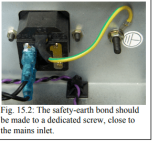
This is how I do it, And I like the ground wire to be even shorter than this- within 10mm or so to the edge of the IEC inlet housing.
Most importantly- for anyone reading this- Is do not connect anything else to the ground pin on the IEC inlet, or to the bolt that the ground wire is bolted to the chassis with. Clean off the paint around the hole that the bolt goes through, and put a lock washer and/or star washer under the nut used to secure the bolt, this way you ensure a tight, strong connection and adequate continuity.
Any additional ground wiring made to the chassis should be to a separate bolt near the IEC ground bolt. Do not share the IEC grounding connections with anything else.
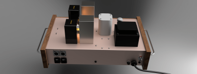
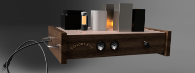
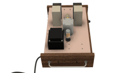
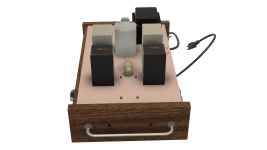
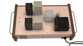
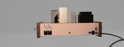
Project Update - Chassis design complete I believe after dozens of hours modelling it in fusion. Went to a standard 10x17 chassis size, but designed my own. Copper on top and front and back and steel on sides and bottom. Copper visible on top and back.
Measure 10,000 times, cut once I hope. There are close to 70 holes in this chassis if not more.
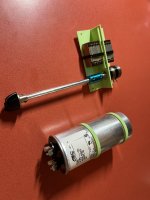
Got the new ASC Shizuki finally a couple weeks ago. Every part you see in the model, I either have on hand and have modelled it, or have designed and built or will build (i.e. wood veneers). I have the copper and steel sheets ready to mill and bend and cut to size for that. I have all the electronics. I am just waiting on the stainless steel rod for the handles I have designed.
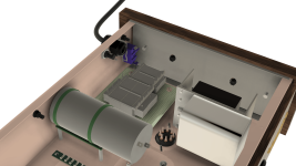
Haven't modelled the wiring in fusion. It's a major pain. I put the signal tube cathode cap and resistor in for fun. Mounting the Sic Safcos I used a tie wrap adhesive cable tie mounts in between the ceramic posts and will use to fasten to other mounts under the top of case.
I have not divided the two halves (transformer and signal) with a copper shield as the jury is out as to whether it is required according to this thread.
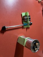
Some screen shots and a few nice renders at the end. Also picture of the shizuki mount and the volume and input transformer mounts I 3D printed.

Measure 10,000 times, cut once I hope. There are close to 70 holes in this chassis if not more.
Got the new ASC Shizuki finally a couple weeks ago. Every part you see in the model, I either have on hand and have modelled it, or have designed and built or will build (i.e. wood veneers). I have the copper and steel sheets ready to mill and bend and cut to size for that. I have all the electronics. I am just waiting on the stainless steel rod for the handles I have designed.
Haven't modelled the wiring in fusion. It's a major pain. I put the signal tube cathode cap and resistor in for fun. Mounting the Sic Safcos I used a tie wrap adhesive cable tie mounts in between the ceramic posts and will use to fasten to other mounts under the top of case.
I have not divided the two halves (transformer and signal) with a copper shield as the jury is out as to whether it is required according to this thread.
Some screen shots and a few nice renders at the end. Also picture of the shizuki mount and the volume and input transformer mounts I 3D printed.
Attachments
-
 fc68df57-f7ed-46b1-b9ae-d6b6b9a2808b.png256.5 KB · Views: 77
 -
 e161451d-fbc3-4870-a829-995596e2b76e.png283.9 KB · Views: 78
 -
 serious pre v56-chassis-inside-end.png460 KB · Views: 72
 -
 serious pre v56-chassic-end2.png215.9 KB · Views: 73
 -
 serious pre v56-chassis-end.png259.9 KB · Views: 73
 -
 serious pre v56-chassis-top.png324.5 KB · Views: 86
 -
 IMG_8863.jpeg633.4 KB · Views: 81
 -
 IMG_8864.jpeg547.1 KB · Views: 81
 -
 serious_pre_case_2023-Dec-05_01-13-15AM-000_CustomizedView16060092642.png172 KB · Views: 80
Can a Copper chasis bear the weight / mass of the transformers without flexing ?
How thick it must be .... 2mm ?
Asking out of curiosity.
How thick it must be .... 2mm ?
Asking out of curiosity.
@krca45 I guess I’ll find out. I believe so. It’s 19 gauge or about 1 mm thick.
Copper Sheet C110 H00 1/8 Hard 32 Oz. 0.043 (19 Ga.)
See
https://www.hammfg.com/electronics/small-case/chassis/1441.pdf
Which is a 20 gauge chassis.
Copper Sheet C110 H00 1/8 Hard 32 Oz. 0.043 (19 Ga.)
See
https://www.hammfg.com/electronics/small-case/chassis/1441.pdf
Which is a 20 gauge chassis.
It’s a good point. If I need I can add a support in the middle which probably would do the trick and also add shielding.
- Home
- Amplifiers
- Tubes / Valves
- "Serious Pre" Tube Build