
This is perfect. I understand it mostly so far. Thanks.
https://darklanternforowen.wordpress.com/2014/01/21/tube-linestage-preamp-the-beginning/
You could check this. It's basically what you are doing. Might be helpful. There are no anode chokes being used here, though.
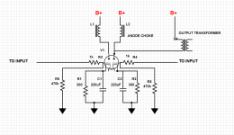
I have put together a very basic schematic but it's just intended to show you the circuit generally.
I don't have experience with balanced interconnects, plate chokes, or input transformers.
The schematic from the first page of this thread shows the output transformer elevated on one side (to approximately B+ voltage) via a 5.8K resistor and a capacitor. I don't know why that's necessary in that design and don't know if it's necessary in yours. (I suspect not).
Heater wiring not shown (though heater connections are on the schematic).
B+ indicates connections from your power supply.
This is your single 5687.
Values are not always an exact match for what you have on hand, but some are not critical:
If your heater transformer does not have a center tap, you will have to create one. That may be why you have "extra" resistors attached to the 5687 tube socket you inherited. As Eduard noted, your heater wires should be tightly twisted. I use an electric drill for that.
Again, this is a rough sketch, and you need to verify all wiring of chokes/transformers per the manufacturer's documentation and guidance.
Eduard provided an image showing a method for star grounding which could be followed.

You could check this. It's basically what you are doing. Might be helpful. There are no anode chokes being used here, though.
I have put together a very basic schematic but it's just intended to show you the circuit generally.
I don't have experience with balanced interconnects, plate chokes, or input transformers.
The schematic from the first page of this thread shows the output transformer elevated on one side (to approximately B+ voltage) via a 5.8K resistor and a capacitor. I don't know why that's necessary in that design and don't know if it's necessary in yours. (I suspect not).
Heater wiring not shown (though heater connections are on the schematic).
B+ indicates connections from your power supply.
This is your single 5687.
Values are not always an exact match for what you have on hand, but some are not critical:
- Grid leak resistor (I show 470k; you indicate 455k)
- Grid stopper resistor (I can't read your writing but it appears to be approximately 1k). Should be as close to socket pin as possible.
- Cathode capacitor value (~220uF is plenty; value can be fudged)
If your heater transformer does not have a center tap, you will have to create one. That may be why you have "extra" resistors attached to the 5687 tube socket you inherited. As Eduard noted, your heater wires should be tightly twisted. I use an electric drill for that.
Again, this is a rough sketch, and you need to verify all wiring of chokes/transformers per the manufacturer's documentation and guidance.
Eduard provided an image showing a method for star grounding which could be followed.
Attachments
Hello,
There is no anode choke.
The grid leak is on the wrong side of the grid stopper.
There is no need to create an artificial center tap or to elevate the heater supply. It will only complicate things
Careful wiring without creating loops is essential.
The way the Lundahls are constructed reduces " interference " with nearby parts. There is an easy way to check this with a basic multimeter. Even the high number of Henry anode chokes did not pick up a bad transformer nearby.
The Cossor need to be checked for correct orientation.
Greetings
I am pretty sure this is what I drew yesterday?

What is wrong with this. Note plus side is down and minus up. 2 is anode 3 is grid.
What is wrong with this. Note plus side is down and minus up. 2 is anode 3 is grid.
Connect B+ to OPT, then OPT to 5687 plate. That is the primary side correction.
You are showing OPT connected to 5687 plate and then to common/ground.
I find it difficult to draw an organized schematic including PSU, tubes, and OPT, so focused only in the triode wiring.
I would connect OPT to B+ from C2.
You are showing OPT connected to 5687 plate and then to common/ground.
I find it difficult to draw an organized schematic including PSU, tubes, and OPT, so focused only in the triode wiring.
I would connect OPT to B+ from C2.
Hello,
You should practice drawing with an exercise like this with real pencil and paper.
The resistor and the cap under the output transformer is the last RC network in the power supply. It does state that it ( just the resistor) is connected to the 265 volt supply. This RC network has been mentioned before because it needs to be adjusted because we have a much lower dc voltage as a starting point.
Just a few hours ago it has been written here that the primary side could act as a kind of final filter for the power supply before it reaches the tube.
Careful reading is hard because people wanna multitask.
This is a very basic circuit but as we can see pretty easy to mess it up. Morgan Jones is to high brow. There are some people on you tube that describe how a very basic tube works using baking popcorn for clarification.
Check the Cossor best position. Will cost half an hour max of your time
Thanks for the clarification, Eduard. I completely misunderstood the schematic there.
I can revisit the PSU sometime later this week but my initial thought is that a separate RC network for each channel is not necessary given that you are using output transformers. They will provide additional filtering (and a small voltage drop). But it is of course something you could do.
I can revisit the PSU sometime later this week but my initial thought is that a separate RC network for each channel is not necessary given that you are using output transformers. They will provide additional filtering (and a small voltage drop). But it is of course something you could do.
Attachments
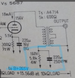
You see,Also in the original Japanese circuit the RC net had a 5k ohm resistor and a 220uf cap I think. Because the power supply was bigger in the original, the 5k is now way less. So as you say maybe 300ohms would work. The 8uf sic safco i assumed was the "C" in the RC net of each channel. I will check back in my records...I don't know what an RC net is. Is that the capacitors and resistors soldered to bottom of signal tube socket?
The high voltage comes from the sic safco 8uf, goes through primary side of the Tango and then enters the 5687. I think this is what my schematic shows.
I just found my records. I have an old tube socket 5687 where i can take the old resistors and capacitors off of the socket. So I will measure them and see what they are as well...
He knew some days ago but then it vanished all the way
Hello,
There is already a lot of info published here about the way to go.
Short connections in the last power supply cap/ 5687 and Tango. But also avoiding making loops. Correct orientation of the Cossor choke. Twisting wires that need to be twisted.
Short connection from Sic Safco to Tango did make a difference in my single ended designs.
Greetings Eduard
Here is the replacement for the Shisuki. Datasheet attached.
It looks like the same specifications. It doesn't seem quite as heavy. It is a "motor run" capacitor which is apparently what is required (vs motor start). If I fail as a tube preamp builder, I can always use in my air conditioner! Apparently, this is where these things are used a lot. I have built a lot of circuit boards, guitar pedals etc. with capacitors, but this is a new world for me. 😎

It looks like the same specifications. It doesn't seem quite as heavy. It is a "motor run" capacitor which is apparently what is required (vs motor start). If I fail as a tube preamp builder, I can always use in my air conditioner! Apparently, this is where these things are used a lot. I have built a lot of circuit boards, guitar pedals etc. with capacitors, but this is a new world for me. 😎
Attachments
- Home
- Amplifiers
- Tubes / Valves
- "Serious Pre" Tube Build