For L1 maybe try half the Henries and half the resistance as it is a 2 coil device and the top rail is only seeing one coil??Okay, here's my attempt at using all the latest values. I've retained the 600 ohm resistor right before the 2nd choke (added 600 ohm to 115 ohm -> 715 ohm total resistance there).
This would represent a single independent RC arm for each channel, each with a 600 ohm resistor and an 8uF cap. I combine them together in PSUD.
I must be misunderstanding something as we are now down to ~100V B+. Otherwise it looks pretty good!.
If I remove the 600 Ohm resistor prior to the second choke, we will regain some voltage. Also if I lower the resistance for each RC section. But I'll wait for final measurements once again.
I cannot find how to simulate a split inductor on PSUD....so the PSUD simulation may not match reality? If it did I think we'd be seeing 223VDC at V(C1) as per my post of it being tested before shipping the power section.
I will keep that in mind if I have issues. What would the symptom be for that?
Don't now for sure - it was general info, what i wrote ( maybe i am wrong in this case but check it - literature, datasheet & PSUD ).
Up'til now i have worked only with solid state rectifiers - will probably go on for tube rectifiers in the future builds.
Hope someone with real experience will comment.

With 600ohm in final RC legs vs 455ohm. Still doesn't get 223VDC at C1 like the picture of the test, but this is looking close...but this is the first time i really try to use psud....

Kind of?
1. Transformer
You measured secondary winding resistance but did not measure primary (AC coming in). That should be added to the secondary resistance of 71.
2. First choke
Lundahl data sheet gives 200Ohm for each coil and ~25 H for inductance. You therefore need to set DC Resistance for the first choke at 400 Ohm with at least 50H inductance depending on the specific choke you get.
3. Final RC: If you want to simulate two RC legs, one for each half of the 5687, and they each have 600 Ohm resistors and 8uF capacitors--yes, that looks good. But Looks like PSUD is showing 0 volts for VC3?
You don't need to "split" the inductor.For L1 maybe try half the Henries and half the resistance as it is a 2 coil device and the top rail is only seeing one coil??
I cannot find how to simulate a split inductor on PSUD....so the PSUD simulation may not match reality? If it did I think we'd be seeing 223VDC at V(C1) as per my post of it being tested before shipping the power section.
Half of the choke is on the (+) rail of your PSU.
Half is on the return (-) or "common" rail side of your PSU.
Simplify down to this:
(TX) / >----->-- 25 H/ 200 OHM -->--- \
\-----<-----25 H / 200 OHM ---<--/ (38 mA)
That is the same as
(TX) / >--->- 50 H / 400 OHM -->- \
\----<----------<--------------</ (38 mA)
Inductors in series add: 25H + 25H.
Resistance in series adds: 200 Ohm + 200 Ohm.
Resistance values are not the same.Thanks so much @Thekak for doing this. Why does mine look different with same values?
Same issue I had with the tutorials....the resistance of the secondary power transformer measured 71ohms. See picture from yesterday.
View attachment 1229141
Voltage of the transformer is not the same.
You need to double-click the transformer section and get to the configuration values. You must get past the first screen which shows resistance and voltage along with the current capability of the transformer. That needs to be .15 Amp (I think that's what I saw earlier from some of your notes). There you will enter 210V and leave regulation at 5%. Click off. The numbers will change slightly. Click OK.
It should not show 210V in your highlighted portion (like it does in this screenshot above; it should show a higher number).
There is more than enough series resistance per plate from the chokes in this PSU alone! Each plate wants at least 150 ohm.Look at the 6X5 datasheet - the transformer secondary resistance is probaby to low for 6X5 anodes - people are putting resistors in for each 6X5 plate when this is the case - the datasheet should tell You what is the minimum plate resistance for the tube so You can go on from there.
Set your current source to 38mA! Not 38A!With 600ohm in final RC legs vs 455ohm. Still doesn't get 223VDC at C1 like the picture of the test, but this is looking close...but this is the first time i really try to use psud....
View attachment 1229264
I noticed that ;-). For the capacitor "resistance" value, my tester measures the ESR and I enter that number.
Here is what psud help says "Also enter the value of the series resistance used for the capacitor."
ESR for SS 8 uf 0.11ohms
ESR for 10uf BIG Cap C1 is 0.11 ohms
ESR for Cap2 40uf C2 is 0.11 ohms
ESR for 237uf cap is 0.16ohms
when I use 500K ohms the graph is a mess. Is the approach above correct. Also I used 230 volts as the supply is 230-210-0-210-230 at 0.15A? Maybe at 36mA voltages even higher?
Here is what I get with your recommendations and values above....
It's getting closer to actual. Would the PSU below be ok? After 0.6 second startup it is steady....??
I got my new socket ready to wire and removed and cleaned some solder off of the old RC parts...
I'll now make a physical wiring diagram of the new dual triode socket with both sides so I don't mess it up when I solder it together. Should be able to re-use all the parts....
Wish i didn't have a 8-6 job right now 🙂

I'll now make a physical wiring diagram of the new dual triode socket with both sides so I don't mess it up when I solder it together. Should be able to re-use all the parts....
Wish i didn't have a 8-6 job right now 🙂
My understanding is that those voltage "overshoots" that settle down are present on each charging pulse and introduce perturbations into the circuit. It looks a bit like ringing.I noticed that ;-). For the capacitor "resistance" value, my tester measures the ESR and I enter that number.
Here is what psud help says "Also enter the value of the series resistance used for the capacitor."
ESR for SS 8 uf 0.11ohms
ESR for 10uf BIG Cap C1 is 0.11 ohms
ESR for Cap2 40uf C2 is 0.11 ohms
ESR for 237uf cap is 0.16ohms
when I use 500K ohms the graph is a mess. Is the approach above correct. Also I used 230 volts as the supply is 230-210-0-210-230 at 0.15A? Maybe at 36mA voltages even higher?
Here is what I get with your recommendations and values above....
It's getting closer to actual. Would the PSU below be ok? After 0.6 second startup it is steady....??
View attachment 1229337
That said, you will have extra inductance and DC resistance in the circuit overall due to the plate chokes. My understanding is also that plate chokes, being inductors just like the chokes in the PSU, will introduce some further isolation between channels and between each channel and the power supply.
It's good enough to prototype for sure.
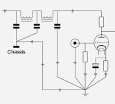
Hi all. I am trying to confirm how the physical wires are connected and compare to circuit diagram.Old Socket with 3 resistors and caps drawing ....
View attachment 1229172
The WH and YL (white and yellow) wires must go to volume?
And there is the ‘post’ that I assume is for ease of connection and the resistors and
Caps all seem to connect there.
On the circuit diagram the ‘down arrows’ do they represent ‘ground’ ? I.e. in post #1.
Hello,
Making things more complicated and everyone will leave.
A clear schematic that could be used how to build things!!
There are some basic rules to follow like twisting heater wiring and creating no loops but '' we '' wasted to much time with psud .
One could talk about how to orientate the Cossor choke and test it by how much it will be '' coupled '' to other iron on the chassis by just using a simple meter ( remember when it was done by a high impedance headphone??) I am sure old members will know.
Greetings, Eduard
Attachments
I don't quite follow how time has been wasted. I also don't know why you are so combative, Eduard. I believe you became upset when I suggested that specific capacitor and transformer brands were not essential to a good sounding preamplifier. But maybe I am misinterpreting your messages.
FusionGuy, do you have a schematic from the person sending you the parts and other design elements? Are they involved?
I have two small children and am not always able to jump in and offer guidance, but will offer what time I have as this proceeds. The only scenario where we have wasted time is one in which the preamp is never completed or functions. But we'll get there.
It will help a lot if FusionGuy takes a break to read up on basic circuit theory for this application. There really aren't very many pieces to this puzzle.
That 450k resistor you mentioned in the other post is probably a grid leak resistor. It goes from grid to ground/common for each half of the triode. You should consult this forum and other resources to see if that value is okay with respect to your potentiometers as well as the input transformers. Personally, I have no experience or knowledge with respect to input transformers and their bearing on this portion of the circuit.
Hi @Thekak
It is essentially the japanese circuit we started at post #1 with, with the new power section we just modelled.
I have written the values of the resistors and capacitors I took off of the old 5687 socket provided to me by the seller and I overlaid that on the diagram. I am trying to decipher the physical wiring and match it to the circuit. I am pretty sure it matches, but as you say, i need to study up on the basic circuit theory. I see Eduard has provided a similar circuit to the signal tube that also shows chasis earthing so I will also study that.
The person I bought gear from provided Japanese diagram and new power supply, but is out of town for several months I believe and unable to assist.
Re input transformers, treat it as SE for now, as I have wiring from Lundahl to attach those to the inputs of this schematic. They should arrive next week. The tangos came in today, and that is already on this schematic (equivalent)
See below. Is left and right equivalent is my question????....physical wiring i found with new overlaid schematic. If so, i think I am good to go.
Note in second picture 455 should be labeled 455K. The resistor i labeled as 400-600 ohms on the leg going to transformer was 5k in the old japanese due to the higher power going in and need to reduce to 160DCV. So I don't need 5k. I will test values to get the voltage down to 160.
The 2K is channel 2 Cathode and the 2G is channel 2 grid. See larger picture below. The WH and YL are color wires i found on the old socket which I am assuming are the input minus and plus - i.e the RCA connector. or the volume and then the RCA.
Does that all make sense?
I'm in no rush. Appreciate the help but no worries on speed.
Will do. Send me something in between "tubes for dummies" and "Einstein's theory of relativity for tube design (Morgan)". The level you speak @Thekak works for me. If there is a book like that, send me the link. I have build CNC machines including the controller box from scratch and guitars and DACs.....but tube stuff is another level...takes a break to read up on basic circuit theory for this application
I'll be offline for a couple of days.....going out of town.
- Home
- Amplifiers
- Tubes / Valves
- "Serious Pre" Tube Build