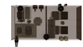
Physical trial layout 9x18" board. I will need the space on the right side for Lundahl input transformer circuit boards....I think
Wood blocks are placeholders for the Tango OPT. Obviously the Lundahl choke (under the plate with four mounting hole to mount to top from underneath) and 1st large cap, meters and Shuzuki go underneath the board. The tall oval shaped 2nd cossor choke goes on top...Sic Safcos are upside down. XLR jacks located in proximity to OPT and input circuits. Those are not panel mount but just a placeholder. Look at that dent Canada Post made in the Shuzuki! I don't risk using it, but here for layout. Need to find another.

Wood blocks are placeholders for the Tango OPT. Obviously the Lundahl choke (under the plate with four mounting hole to mount to top from underneath) and 1st large cap, meters and Shuzuki go underneath the board. The tall oval shaped 2nd cossor choke goes on top...Sic Safcos are upside down. XLR jacks located in proximity to OPT and input circuits. Those are not panel mount but just a placeholder. Look at that dent Canada Post made in the Shuzuki! I don't risk using it, but here for layout. Need to find another.
"It's a dual triode...one tube can do two channels by splitting it. Apparently most people DONT use it like this....I am sure my diagram could still be incorrect...that's why I have 4 tubes"
Your CAD layout shows one tube!!!?
Remember one 5687 "tube" houses two triodes.Ideal for a stereo implementation.
Basically everything for V5 is repeated in V6.V5 and V6 are one tube 🙂
View attachment 1228894
OK! AHA moment. Now I get it. I meant I bought 4 tubes in case I blow one up. I only plan to use one and have some spares 😎 😎
Thank you for clarifying this....I would have labeled it 5A and 5B 🙂
Last edited:
That big cillindrical cap in the middle is really in bad shape ( + the tube broken ) - i would check the cap if it works ( and really try to get the vendor to send all broken again - it's just bad packaging... and i've seen some lousy packaging techniques from some tube vendors ).
You can hardly blow a tube - it's not a transistor 🙂
You can hardly blow a tube - it's not a transistor 🙂

The cap measures ok on my smart tester but because it contains some flamable stuff according to label I’m going to play it safe and not use it.That big cillindrical cap in the middle is really in bad shape ( + the tube broken ) - i would check the cap if it works ( and really try to get the vendor to send all broken again - it's just bad packaging... and i've seen some lousy packaging techniques from some tube vendors ).
You can hardly blow a tube - it's not a transistor 🙂
I'll be curious to see what all of the resistance measurements for your chokes and transformers is. I don't see a great PSU coming out of those raw materials. I have never built a choke input PSU, but also I have never been able to figure out how to use two chokes. Given that you already have so much iron, I'd consider removing one just to simplify things and save space. I'd also love it if someone could offer guidance on how they might build a PSU with 50H choke input (unknown DCR), a 10uF cap, another choke (I don't recall seeing Henries given here), and a 40uF cap. Also a resistor of 600ohms but no other cap values given.
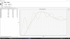
So here's the simulation I have just throwing random DCR and H values in for transformer and choke:

That looks atrocious. I had something like that once and it didn't perform very well.
Again, if someone can demonstrate how that would work out, I'd appreciate it.
Here's the same approach but using the 600 ohm resistor between the two chokes and upping C2 to 80uF:

I show 2mV ripple here at ~145V.
Here are a couple nice and simple suggestions:

A lot of this depends on the DC resistance of your components, so figure that out! (Capacitors not so important and we can just guess here)
You could build this as a single B+ rail or parallel (one for each channel) after the 10uF cap.
I'm showing ~25mV ripple on this. at ~151V. That should be fine but others may disagree.
The LCRC PSU has a faster time constant and should sound snappier.
The LC(R)LC PSU is a bit slower and will sound softer.
My favorite metaphor for PSU behavior was clay vs grass vs concrete for tennis (or some other sport). Best to try a variety of approaches and see what works. In your case this obviously won't be possible unless you have an extended prototyping period.
If you do, you could even build using a bridge rectifier to see what a good solid state PSU would sound like. Seeing as you're building a class A preamp, the power supply's behavior will inform a large portion of the preamp's output.
So here's the simulation I have just throwing random DCR and H values in for transformer and choke:
That looks atrocious. I had something like that once and it didn't perform very well.
Again, if someone can demonstrate how that would work out, I'd appreciate it.
Here's the same approach but using the 600 ohm resistor between the two chokes and upping C2 to 80uF:
I show 2mV ripple here at ~145V.
Here are a couple nice and simple suggestions:
A lot of this depends on the DC resistance of your components, so figure that out! (Capacitors not so important and we can just guess here)
You could build this as a single B+ rail or parallel (one for each channel) after the 10uF cap.
- 2 Channels would be done with a single 40uF cap + a single 300ohm resistor per channel.
- You could also build it with a single B+ leg just as shown and I think it would work fine.
I'm showing ~25mV ripple on this. at ~151V. That should be fine but others may disagree.
The LCRC PSU has a faster time constant and should sound snappier.
The LC(R)LC PSU is a bit slower and will sound softer.
My favorite metaphor for PSU behavior was clay vs grass vs concrete for tennis (or some other sport). Best to try a variety of approaches and see what works. In your case this obviously won't be possible unless you have an extended prototyping period.
If you do, you could even build using a bridge rectifier to see what a good solid state PSU would sound like. Seeing as you're building a class A preamp, the power supply's behavior will inform a large portion of the preamp's output.
Attachments
Here is the cossor closeup with values marked by manufacturer. And on my machine it measures 119ohms. The seller measured 115 and marked it with tape.


Last edited:
Here's the lundahl dual coil choke (LL2743).....and datasheet for the measurements you want. But you wire it like the snapshot from another Lundahl filament current choke (1694).
So it's an anode choke being used differently in the PSU. Apprantly the return ground coil is the secret sauce (common mode rejection maybe???) if i recall correctly from what I have read.
If you look at my latest hand drawn schematic, this is how it is actually wired when I received the PSU mostly wired up. With different pin numbers because you have to look at the 2743 for the proper pins. 1694 is a six pin. 2743 is only 4 pins.
Attachments
That Lundahl choke is really cool.
I'll rerun the simulations once you figure out your transformer DC resistance.
I'll rerun the simulations once you figure out your transformer DC resistance.
From what I understand it is intended to split into two feeds for the output transformers with their own RC net after the shizuki 40uf cap. So I am no sure what the description for that is. See the block diagram picture here....You could build this as a single B+ rail or parallel (one for each channel) after the 10uF cap.
The two large sic safcos are 8uf.
How do I do that?That Lundahl choke is really cool.
I'll rerun the simulations once you figure out your transformer DC resistance.
The PSU circuit was described to me as being like the one below in the picture - but "the second resistor will also be a choke". After the second choke a cap (shizuki) and then left and right side will have a separate network....i assume R2,R3 C3,C4 are the RC net for each output channel. I think R1 below is the second choke in my diagram giving 115ohm resistance in effect.
This doesn't show the dual coil first choke however....that was described separately.

This doesn't show the dual coil first choke however....that was described separately.
Also in the original Japanese circuit the RC net had a 5k ohm resistor and a 220uf cap I think. Because the power supply was bigger in the original, the 5k is now way less. So as you say maybe 300ohms would work. The 8uf sic safco i assumed was the "C" in the RC net of each channel. I will check back in my records...I don't know what an RC net is. Is that the capacitors and resistors soldered to bottom of signal tube socket?
The high voltage comes from the sic safco 8uf, goes through primary side of the Tango and then enters the 5687. I think this is what my schematic shows.
I just found my records. I have an old tube socket 5687 where i can take the old resistors and capacitors off of the socket. So I will measure them and see what they are as well...
Last edited:
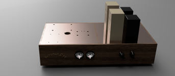
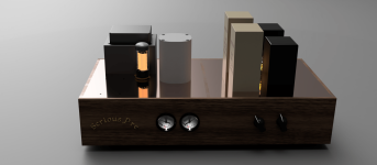
The layout is coming along better. Here are a few shots....I think i now have room to change tubes.

Attachments
Measure resistance from one 210V secondary wire to the other. You can also measure resistance between the primary wires you're using.How do I do that?
There's a 40K resistance (4x10k) after C1. I can send you the picture in case my schematic is wrong. Its the 4 green resistors across the big 1st cap.Here's the same approach but using the 600 ohm resistor between the two chokes and upping C2 to 80uF:
Measure resistance from one 210V secondary wire to the other. You can also measure resistance between the primary wires you're using.
That is R1 10uF cap with 4x10k greenies across it.

Physically i drew this from the PSU hardware received

Physically i drew this from the PSU hardware received
@Thekak I am in Canada and the mains are 120VAC here. Just making sure you know. The PSU is built for 120VAC.
I don't know how to use the PSUD modeler well. I really thank you for doing this. I followed the tutorial someone sent and got different output that the tutorial screenshots. So I am doing something wrong....
I don't know how to use the PSUD modeler well. I really thank you for doing this. I followed the tutorial someone sent and got different output that the tutorial screenshots. So I am doing something wrong....
I recognize where this came from!The PSU circuit was described to me as being like the one below in the picture - but "the second resistor will also be a choke". After the second choke a cap (shizuki) and then left and right side will have a separate network....i assume R2,R3 C3,C4 are the RC net for each output channel. I think R1 below is the second choke in my diagram giving 115ohm resistance in effect.
This doesn't show the dual coil first choke however....that was described separately.
View attachment 1228952
RC -> Resistor Capacitor
LC -> Inductor (L) Capacitor
As shown in the schematic above: LCRC (B+ to power tubes) RC x2 (to driver/input tubes).
The extra RC per channel gives you extra channel separation.
Looks good! I can run new sims tomorrow.
- Home
- Amplifiers
- Tubes / Valves
- "Serious Pre" Tube Build