I am building a tube preamp to go with my custom built Turntable and DAC .... I know nothing about tube amps - everything I know I learned from another forum user on DIY who told me I should build a "serious preamp" and helped me source parts. I'll let him identify if he wants to, but he was ok for me to share.
Will need more help and advice along the way as this is a tough project I think for me. I'm calling it "Serious Pre" in honour of the inspiration.
Overview
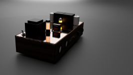
Fusion360 Mockup (not actual parts but rather conceptual right now)

Based on this April 1993 circuit with substantial? modifications provided to me by the DIY inspiration user ....no Phono stage, single 5687 for both channels, etc.

Will need more help and advice along the way as this is a tough project I think for me. I'm calling it "Serious Pre" in honour of the inspiration.
Overview
- Single input (SE or balanced), Single balanced output (could be SE if desired but who would want that!)
- Two volumes - one for each channel therefore balance not required.
- Simple design derived from Japanese magazine April 1993, one signal tube (5687) split for both channels, 3 resistors and one cap for each channel
- Power transformer re-purposed from vintage Kenwood W-24 amplifier, One rectifier (6x5 tube) Two new mouser transformers for heaters
- Tango output transformers (anyone know how to source them from Japan online?)
- Vintage caps, resistors, voltage and amp meters, tubes
- Tocos Cosmos pots
- zero extraneous components that aren't needed to improve the SQ (but the meters are cool and vintage)
Fusion360 Mockup (not actual parts but rather conceptual right now)
Based on this April 1993 circuit with substantial? modifications provided to me by the DIY inspiration user ....no Phono stage, single 5687 for both channels, etc.
Attachments
Last edited:
Well .... I don't know about that one.
In the power supply, the chokes are in the wrong place for starters. It seems to be based on 1950's thinking and we have come such a long way since.
You should never need a 5AR4 to power a couple signal tubes either. Seems lie audio excess audiophile style where performance is secondary to "the story".
It should be fun to build - enjoy!
When the alternative was selenium rectifiers, a 5AR4 was a godsend.
Chokes in the wrong place? Maybe not back when the ESR on the caps was high (1950’s thinking). It is a wee bit lower now. A few good caps and a mosfet - and no hum no noise no nothin’.
Chokes in the wrong place? Maybe not back when the ESR on the caps was high (1950’s thinking). It is a wee bit lower now. A few good caps and a mosfet - and no hum no noise no nothin’.
Well, not really. For a preamp, a 6CA4 or 6BW4 was fine. Or a couple lower current half wave rectifiers as was common practice earlier in time.
Besides, a resistor and silicon diode works great! But chokes work on varying current, that's where they are the most effective. Once you have the variations smoothed out the choke quite frankly isn't much better than a resistor.
Besides, a resistor and silicon diode works great! But chokes work on varying current, that's where they are the most effective. Once you have the variations smoothed out the choke quite frankly isn't much better than a resistor.
Great. Thanks for feedback. Like I said, the circuit I'm building is significantly modified. 5AR4 is a 6x5. Phono section won't be there. Different power supply and choke config.
I will post a hand drawn schematic of what I'm building....
I will post a hand drawn schematic of what I'm building....
That's more like it!
The 6X5 is often found in test equipment. It's a nice rectifier. You don't need monster capacitance either. It would be nice to see what you're thinking of.
If it were me, I would definitely use a solid state voltage regulator circuit.
The 6X5 is often found in test equipment. It's a nice rectifier. You don't need monster capacitance either. It would be nice to see what you're thinking of.
If it were me, I would definitely use a solid state voltage regulator circuit.
In a recent Aikido scratch build, I used v4lve lover's 6V in > 6V out PCB for the signal tube filaments. It's a nice gadget that avoids the need for an extra filament transformer, and also sounds excellent. You can search for them on the forum. For the power supply I used a 6X5 rectifier with a single cap and a Neurochrome Maida regulator board. It isn't cheap, but you can get rid of all those chokes and extra caps, the voltage range is highly adjustable, only 15VDC headroom, and it sounds very, very good. You can always resuse it in a different project. Just a suggestion! ;-)

Here is a very crude schematic. The 5687 is a dual triode and can support two channels if wired correctly. That is my plan. The chokes and RC Net is a black box to me, but I'm working on figuring it out. I've put in the black box the components that will go in there. There is also rectified wiring to support two lit up Voltage and Amperage meters. I haven't shown that wiring - just the secondary tap for it.

sig safco 10uf caps actual size now and more representative
Tango output formers actual size now and more representative


Tango output formers actual size now and more representative
Serious About Valve Amplifiers....read this book

Then this book

And you'll build ever better !!!!!
Then this book
And you'll build ever better !!!!!
With those Tango's what about a headphone output?
We're getting serious now aren't we.
We're getting serious now aren't we.
Type | Primary Impedance | Secondary Impedance | Freq.response -2dB, 4V, rp=Zp | Primary Inductance | max. DC- current | max. output amplitude | Weight |
NP-126 | 10K 20K | 0-75-150-300-600 0-150-300-600-1K2 | 20Hz-30KHz Ib=10mA | 110H Ib=10mA | 20mA | 10V (20Hz) | 0,8Kg |
Also use PSUD2 to design the power supply. Highly recommended. For manual calculation, you can find guidance at https://a-direct-heating-triode.blogspot.com/2018/06/lcr-phono-preamp-part-3.html
I'm seeing signs of over-fetishization of specific types/physical "sizes" of capacitors and transformers even before you understand where you are going. Maybe you and your friend have a lot of money. If so, you are free to spend as much as you want. But IMO there is no reason to go nuts about capacitors or the output transformers.
I don't know where the 10uF caps you are intending to place on top of the chassis are supposed to be in the schematic. Highly recommend that you don't go crazy and over-fetishize specific capacitors and aim for something which will fit inside the chassis and simplify your life.
Also, are you drawing a + 160V supply with a -160V supply? Why do you need a +/- supply here?
Personally, I would reconsider the usage of the Tango transformers. Just don't see why you need to go through the trouble and expense of ordering them. Hashimoto are going to be easier to acquire and less expensive. You are already considering a Lundahl choke, so why not one of theirs?
Unless you can A/B a capacitor or transformer in real-time, you will never know the difference. And if you were to build two identical preamps with differing capacitors or transformers, then switch between them as you listened, the difference would truly be minute (and perhaps even imperceptible).
Work on the fundamentals and then obsess over the %.0005 difference you will achieve in sound with capacitors/transformers.
Me too, and that's what I use myself. You need the 1,200V Schottky diodes. Cree and others.If it were me, I would definitely use a solid state voltage regulator circuit.
PSU capacitors are important. I seriously recommend a DC Link polypropylene cap in first and last positions. I use Kemet C4A but there's also Vishay and a couple of others. Electrolytics in between is OK. This will make an audible difference - I've laboriously A-B tested PSU caps and that's my take on it.
I'd use a type 26 in filament bias but that's another kind of build. Otherwise I'd use a pair of 6AH4.
Member
Joined 2009
Paid Member
Well, it's a nice tube the 5687, some hints of 6SN7 linearity and designed for industrial use it has some balls so nicely suited for driving a transformer output. A very good cap might be better but it's a matter of taste in the end. I totally get that you want to reproduce a design that has grabbed your attention - it doesn't matter that there are many ways to skin a cat, some better than others but if the heart wants to Tango then Tango is what it wants. Nobody else will really hear the difference but you alone will know what is under the hood and why it's there and the satisfaction from that will last longer than the pain of opening your wallet.
I can see the use of a 5AR4 because it's an indirectly heated rectifier so it allows a safe warm up speed for B+, it also has a relatively low voltage drop and I like that for reduced sag. Nevertheless, a noval rectifier has been recommended above and I endorse that approach but it really depends on what heater winding you have on your power transformer which already has been mentioned as being good for a 6X5 so good idea to use that.
Overall, it's a circuit I'd build myself if I didn't just finish my own high-end pre-amp with tubes. I used an EZ80/81 rectifier as my build was all noval. And I also used SS rectified and voltage-regulated heater supply to eliminate all worries about noise coupling through the heater-cathode capacitance or from wiring dress.
My line-stage provides about 20dB of gain which is nice but these days you don't often need it. I have a -20dB attenuator I can switch-in as pre-amps really aren't necessary for gain very often. So one thing you can think about is dropping the cathode bypass capacitor (there will be an increase in effective plate resistance to think about).
Last edited:
Nothing particularly wrong with either the circuit or the PS imho. Had a very similar preamp, apart from a regulated B+, many years ago. Today, the amount of second harmonics such circuits generate is no longer to my taste.
it has some balls so nicely suited for driving a transformer output. A very good cap might be better but it's a matter of taste in the end.
The transformer is the one providing balls here, with a cap the output impedance is borderline unusable in a line stage. The transformer trades voltage for current.
Member
Joined 2009
Paid Member
depends on load (driving a tube amp?), depends on this, depends on that. Check out the Salas 6V6 cap output. All depends on the load.
I think the way I drew the modifications (hand drawn circuit) is not correct. Someone said I will blow myself up if i use that one ! The original Japanese circuit is real. I am losing the Phone stage, using a Kenwood TRIO PS and two separate heater transformers and different chokes. I will try and get my hand drawn circuit fixed. I am tube "Newbie".Nothing particularly wrong with either the circuit or the PS imho. Had a very similar preamp, apart from a regulated B+, many years ago. Today, the amount of second harmonics such circuits generate is no longer to my taste.
- Home
- Amplifiers
- Tubes / Valves
- "Serious Pre" Tube Build