Ok thank you very much now I’m waiting on the driver that burned and I’ll should be able to post a picture of the amp completed
So let me get this right if I add a .22 ohm resistor to the output then if I by accident short out the outputs it won’t blow the transistors ?
It will help protect against a short under no signal conditions because the amp will be able to maintain its DC conditions.So let me get this right if I add a .22 ohm resistor to the output then if I by accident short out the outputs it won’t blow the transistors ?
100% safe. Tweeters are usually AC coupled via the crossover in the speaker and so DC offset usually has no effect on tweeters, it is high frequency oscillation that kills them.Hey guys is a dc offset of 50mv safe for speakers and tweeters ?
It is usually determined by the DC balance of the differential input stage. If the offset is below -/+100mv it is a non issue.Also can you tell me which of these resisters controls the dc offset ?
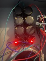
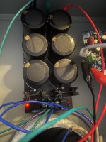
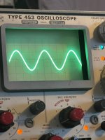
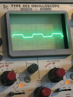
Another question this is a weird one on the psu I have two led light they indicate that the caps have power . Now when the amp is connected one led turn off faster then the other indicating that there is more load on one side then the other . I checked the current on the ground side and there is 1.5ma indicating that there is an imbalance in the circuit it was not like this before both LEDs used to turn off at the same time . Am I overthinking things or is there an imbalance in the circuitry ? Just to test it further I ran a 1khz sine wave through the amp and measured it with the oscilloscope and I can clearly see that one transistor is shutting down before the other ! Could this be a miss match of the output transistor? Maybe the hfe is different one to the next would that effect it ? On the pic with the oscilloscope you can clearly see that the top portion of the wave is at zero but the bottom portion is got some potential still . The only thing I can attribute this to is a miss matched output transistor but I could be wrong !
Attachments
Last edited:
Nothing to do with the transistors at all. The current draw will be different from each rail (normal) and when you turn off one rail therefore collapses before the other.
All normal.
All normal.
I’m actually turning them both off at the same time one just collapses faster than the other ! There is a difference of 1.5ma which I see on the ground but it used to read zero before !
Its all normal, really 🙂
Each amp will draw slightly different currents, you can't expect the - and + rails to fall at the same rate when you turn off. Also if you have a load attached then the DC offset will shift as the collapse and that will pull one rail down much faster than the other.
Each amp will draw slightly different currents, you can't expect the - and + rails to fall at the same rate when you turn off. Also if you have a load attached then the DC offset will shift as the collapse and that will pull one rail down much faster than the other.
I think you misunderstood me I’m only testing one amp the other amp is not connected I was just curious why one rail was draining faster than the other when the entire circuit is made to be balanced ! And no there was no load connected ! The only thing I have changed is the 10ohm resistor I put a 2w instead of a 1w I thought maybe that had something to do with it . As soon as I get the parts to complete the second amp I’ll compare the two see if there is a difference.
The current draw from each rail can be different in an amp. I don't think this one is balanced meaning each halve is a mirror image of the other, it has a differential input stage but that's all.
Also large caps such as the PSU one can have a wide tolerance, a close tolerance for big caps would be -/+20% and they could be as much as -20/+50% and those differences mean each rail holds more or less energy than the other at switch off.
Its all a non a problem.
Also large caps such as the PSU one can have a wide tolerance, a close tolerance for big caps would be -/+20% and they could be as much as -20/+50% and those differences mean each rail holds more or less energy than the other at switch off.
Its all a non a problem.
D
Deleted member 550749
Balance mean?? Did u adjusted exact equal bias, offset ?? Also transistor r not same at all , difference in power draw, so u can't do anything with it just do only one try to set equal bias and offset and enjoy don't do extraordinary things with ur amp 👍
I don’t have any adjustment for bios . I just noticed that the psu led on one goes out faster than the other and I check current on both rails and one is drawing a bit more current than the other rail . As you can see one rail goes out faster than the other I just want to know why this wasn’t happening before !
Attachments


The current draw from each rail can be different in an amp. I don't think this one is balanced meaning each halve is a mirror image of the other, it has a differential input stage but that's all.
Also large caps such as the PSU one can have a wide tolerance, a close tolerance for big caps would be -/+20% and they could be as much as -20/+50% and those differences mean each rail holds more or less energy than the other at switch off.
Its all a non a problem.
I’ve checked to see if the caps are turning off at the same rate and yes they do when there is no load or amplifier connected ! It has two drain resistors that drain the caps and they discharge at the same rate !
D
Deleted member 550749
Sorry I thought, 1 Chanel of amp consuming more power, 🤣 sorry for that, I think voltage dropping at one side , check idle consumption, while using both rail voltage drop, if it's huge then this is not good, not good mean - if ur +rail is 40 an -rail 30-34 that's not good , that's why we ad trim pot for adjustment bias and offset 😜
D
Deleted member 550749
Ur oscilloscope showing Ac wave dominating more at negetive side 🤔 i don't think it's good negetive will clip first then positive that's not good
Last edited by a moderator:
Provided the amp has low offset and no oscillation you haven't a problem.I’ve checked to see if the caps are turning off at the same rate and yes they do when there is no load or amplifier connected ! It has two drain resistors that drain the caps and they discharge at the same rate !
What happens in the time the rails collapse isn't a meaningful measurement and is simply a non valid test. As I have said, lots of amps draw differing currents from each rail.

The reason why the oscilloscope is showing an imbalance is I had already unplugged the transformer! So the voltage was already sagging on one rail !
Is what normal? You mean differing current draws from the rails... yes that is absolutely normal in many amps.#mooly is that normal??
- Home
- Amplifiers
- Solid State
- MX50SE problem please help