Does the ACP+ do 4Vpk? The 32 Ohm output impedance would be nice to have.
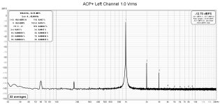
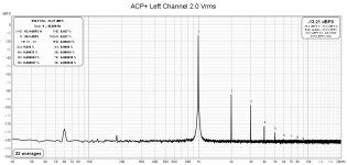
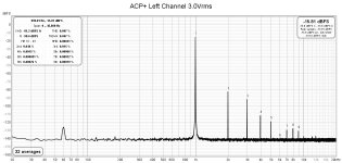
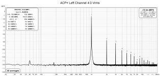
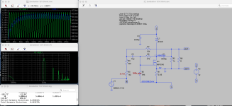
Here some measurements that I did last year. It can do more than 4Vpk.
Attachments


The Meanwell has a 3 prong power cord, you would be better off with an isolated 2 prong power supply like recommended in the BOM. (It prevents ground loop)Jim, do you have a part number for the 12VDC power supply you show in the build guide pics?
Have found the Meanwell GST60A12-P1J - which is a 5Amp unit - I assume this will suffice?
Each channel seems to be bias at 0.9Adc (0.5V across 0.56 ohm resistor) so I’d aim for 12Vdc, 2A or 2.5A for each monobloc.
EDIT; Just noticed that the BOM is showing a 12V, 3A power supply.
BR
Eric
Last edited:
Grounding the minus of the supply has the potential for non operation.
BigBadaBoom, or at least short sizzzzzzzzle! event

(amp's V- is (0R56*Iq) bellow amps GND)

checking startup is for Sissies
we, brave builders, we are just flippin' damn power switch!!

we, brave builders, we are just flippin' damn power switch!!
BigBadaBoom, or at least short sizzzzzzzzle! event
(amp's V- is (0R56*Iq) bellow amps GND)
Say you wanted to build a linear supply and a chassis (bigger heatsinks) with an earth gnd, do you just use a bridge/10R resistor to earth for audio ground? And then just leave -V floating?
GND is state of mind
though, always best to respect state of mind of Constructor
so, in this case too, you can either short audio gnd to case, or "elevate" through regular ways - be it solo NTC or combined with bridge
-V is -V; negative leg of PSU, which is not declared and used as GND
so, yes, as Pa sez - important is not to use switchers having neg leg shorted to its case, thus resulting in short with chassis/safety GND
Nelson, do you have a part number for the recommended 12VDC power supply - no part number is mentioned in the BOM in your article.
Want to make sure I get one that is functional with the amp.
Want to make sure I get one that is functional with the amp.
It won't break, it just won't bias up.

now you realistic ..... lost sense for drama just for a moment .....
Nelson, do you have a part number for the recommended 12VDC power supply - no part number is mentioned in the BOM in your article.
Want to make sure I get one that is functional with the amp.
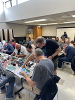
This is the PSU used in the Amp Camp.
- Home
- Amplifiers
- Pass Labs
- Zenductor