There are more questions than answers in those graphs.Intermodulation distortion from AC heating of DHTs?
Here's a good example of AC heated 300B PP at 1W output is shown in the Post by Euro21 (picture at the right-side).
https://www.diyaudio.com/community/threads/sound-of-300b-set-by-satoru-kobayashi.258870/post-4030013
If you measure this intermodulation yourself, you can experiment with the music signal level, and see that it increases more rapidly as the signal amplitude reaches higher.
The post also shows a DC heated SE 300B at the left.
Intermodulation at mains frequency (50 Hz) is -50dB, whereas intermodulation at double the mains frequency (100 Hz) is -65 dB. Shouldn't it be the other way around? Dominant 1x mains frequency intermodulation is consistent with circuit picking up hum from AC filament supply, which intermodulates with the 1000 Hz signal.
I haven't seen any evidence for 2x mains intermodulation from AC fiament being different from general intermodulation, e.g. drum intermodulating with guitar. Design amplifier for low IMD, and AC filament stops being problematic.
If you were responding to my post, I did draw it out (assuming a floating supply with no specified DCR) and didn't see why cathode current (ie. "the sum of screen , plate etc. currents) would be necessarily greater from the negative end of the filament than the positive "regardless where the cathode is grounded".This is a Physics "electric field" problem.
Anything less than that, prevents an understanding of the cause.
I guess someone needs to draw out something better than just a simple tube base diagram.
Want to try thinking about it in another way . . .
Draw out a DC powered filament, and a Plate, all in a glass envelope.
It does not get any simpler than a Diode!
No grid is necessary to prove both the theory, and the actual measured results.
"You should make things as simple as possible, but no simpler." - Albert Einstein
We are already at Post # 80
Good Luck!
Nor do I understand why signal current would necessarily pass through the power supply if the positive end of the filament is grounded. I'd like to understand so am asking for some clear graphic representation, whether drawn by a member or taken from a publication.
Kay says "It can be easily shown in an experiment . . . ." and I take him at his word, but the details of the experimental set-up would be needed if I'm going to repeat it.
Thanks
Last edited:
That is disappointing, I had hoped to compare the IMD results of an Amp with a DH cathode such as a 2A3 on AC. It seemed like you had amassed & recorded quite a bit of information from real tests on many amps as quite a few of we fossils did in the past. Maybe not.The next time I am at my friends lab who has a HP3585, and if an amplifier such as a 2A3 or a 300B single ended amplifier with AC filaments is available, I will take a picture and post it.
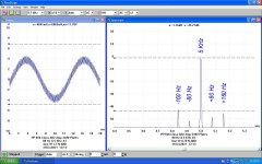
NTL, here is a typical test done by the SMPTE standard, along with a description of how the test is done for those unfamiliar. In this report the test was done by using a Pico Technology 3224 with 12-bit resolution. So the dynamic range is 72 db, sufficient for most ordinary audio testing. The LF at 80 Hz is 12 db higher than the 5 KHz test tone but not visible on this trace.
Since the LF I used was 80 Hz any PS ripple would appear as side bands on the trace, something measurable by this method but not possible with the HK & other low cost IMD testers of the past. The HK could not separate a PS problem from ordinary IMD at 50 / 60 Hz Etc.
Attachments
Alright, Ian, you shall have it! Happy to publish what I have on the effect of AC-heat vs. DC heat, implemented ith my regulators.I would have thought the opposite . . . . . that you had done your research for development of the obviously successful supply circuits and you were basing your statements on first hand knowledge.
To address your previous criticism, I took fresh measurements to use the same amplifier, same EML 300B DHTs - with no changes other than the filament supply:
- AC heat, with 2x 33Ω resistors forming the usual centre-tap; Toroidal 30VA PT, mounted >1m from the amplifier, and away from any other PTs or chokes.
- DC heat, same amplifier, same EML 300B valves heated with the latest RC-V9 regulator.
The marker in the DC spectrum shows no spur at 950Hz above a noise floor 110dB down from the 1kHz signal 50Hz mains supply).

The same thing appears in my own measurements. Locating the transformer far from the amplifier (>1m) made no notable difference. If it is a case of general pickup, I see no reason why the DC solution would not be susceptible too, since that would be a common-mode effect.Intermodulation at mains frequency (50 Hz) is -50dB, whereas intermodulation at double the mains frequency (100 Hz) is -65 dB. Shouldn't it be the other way around? Dominant 1x mains frequency intermodulation is consistent with circuit picking up hum from AC filament supply, which intermodulates with the 1000 Hz signal.
OTOH, coupling from the AC-heating current in the filament directly into the grid would explain it perfectly. I believe @6A3sUMMER mentioned this earlier.
My EML have high quality build compared to many other 300Bs; but I could try Western Electric 300B as an alternative, if I get a moment.
I have measured AC vs DC (my RC-V9 regulator) in the same amplifier, using the same tools, at the same time.
The AC-heated measurement is close to Bela's (Euro21) spectrum, especially given the differences in the amplifiers.
Rod - now this is the right way to do the comparison: AC vs. DC heating the only variable. As you interpret your data, the source of intermodulation is AC across the filament leaking into amplifiers input. Does it mean that the theory of 2x mains frequency IM is wrong? Would be easy to test - feed filament with clean filtered AC and see what happens with spurs at mains multiples.
Thanks Rod. Sorry 'bout that. I didn't mean to drive you into more work. . . . . . . but you must admit, your examples make a better illustration. : )Alright, . . . . . . . . .
Last edited:
Hearinspace,
When I look at Rod's spectral display, even my old eyes see multiple sidebands on both the 1kHz tone (-100, -50, +50, + 100Hz),
and the 2kHz tone (-100, -50, +50, + 100Hz).
Even the sidebands around the 3kHz tone looks pretty dense to me.
Some Power Mains IM is at 1X and some Power Mains IM is at 2X.
Note: On the 2kHz tone, the 100Hz sidebands are stronger than the 50Hz sidebands.
Just saying
Last edited:
I really can't see how IM from the presence of mains frequency and signal frequency is any different within a valve than from any other case external to a valve. Signal plus mains frequency can only generate the same predictable output spectra. This idea of doubling may have come from an earlier (since disproven) model of varying filament temperature with instantaneous mains voltage. If I'm missing something I'm all ears, but just can't see it.
All good fortune,
Chris
ps: this implies that IM from this source could be cancelled by paralleling or push-pull.
All good fortune,
Chris
ps: this implies that IM from this source could be cancelled by paralleling or push-pull.
When I saw the effect on 2A3 or 300B, the only sidebands were at 2X.
I do not know if I will ever build another 45, 2A3, or 300B single ended amp, with AC filaments.
I can not remember all the details, but the 2X frequency from full wave B+ rectification was not the cause of the sidebands.
Of course full wave ripple would normally be the obvious cause, but we did something to rule it out as the cause on those amplifiers
(like reducing the ripple by 6dB, and the sideband's amplitudes stayed the same).
Last edited:
Your wording makes me wonder, do you think I'm denying there's an effect? I'm not. My sole issue with Rod's statement was his reference to diagrams not comparing apples to apples. He posted new images and I thanked him.When I look at Rod's spectral display, . . . . . .
My question remains about Kay's post , finding it difficult to see as an absolute rule. That's all. Just finished downloading a searchable version of Deketh's book and will look through it tonight.
Thanks
I believe that the 50Hz AC waveform finds its way to influence the anode current in two ways.Rod - now this is the right way to do the comparison: AC vs. DC heating the only variable. As you interpret your data, the source of intermodulation is AC across the filament leaking into amplifiers input. Does it mean that the theory of 2x mains frequency IM is wrong? Would be easy to test - feed filament with clean filtered AC and see what happens with spurs at mains multiples.
Firstly by the varying (at once) Vgk and Vak: this yields a (more or less nullable) 50/60Hz component; this in turn generates the 100/120Hz component by the natural 2nd harmonic distortion of the triode, and is measurable because of the large signal input (7.071V pk) and it not nulled, even in PP or with careful humpot balancing.
The only other measurement I could get to alter the spectrum was by decreasing the value of the cathode bypass capacitor all the way down to 30µF (was 270µF). This caused the 50Hz spur and the 50Hz sidebands to increase, while the 100Hz and its sidebands were largely unchanged.
Secondly contributor to the input:
- the grid - being so close to the filament - must pick up some voltage induced by the field from the heating current. I would expect this to be 50/60Hz. I believe @6A3sUMMER knows something about this from previous posts.
The IMD is generated just as you say, but the anode current also has second harmonic content from distortion of the triode, since the input is a large signal. It's the second harmonic of the anode current that gives us the 100/120Hz spurs.I really can't see how IM from the presence of mains frequency and signal frequency is any different within a valve than from any other case external to a valve. Signal plus mains frequency can only generate the same predictable output spectra. This idea of doubling may have come from an earlier (since disproven) model of varying filament temperature with instantaneous mains voltage. If I'm missing something I'm all ears, but just can't see it.
The IMD driving waveform is somewhat unusual, as the heating waveform also forces Vak to follow the AC, combined with changes in anode current from Vgk.
Yes it is useful sometimes, to be provoked into doing things that are really necessary!Thanks Rod. Sorry 'bout that. I didn't mean to drive you into more work. . . . . . . but you must admit, your examples make a better illustration. : )
Simple straight-forward orientation. Thanks for posting it.here is a typical test done by the SMPTE standard, along with a description of how the test is done
PS. In the test description where it says , "combined in a simple resistive network" , is that a Wye summing network ? (For example as described by Rane here?)
The sidebands also visible, if the filament DC not enough clean.
This sample is the 300B SE (6W, 8R). Filament heating is DC, but only use graetz and 2x10000uF smoothing capacitor.

The output tubes EH300B, but the "green" is the standard, the "red" is gold grid.
This sample is another 300B SE (Chinese tubes -higher THD, than expected-, 8W, 8R), R.C regulator V.4.

This sample is the 300B SE (6W, 8R). Filament heating is DC, but only use graetz and 2x10000uF smoothing capacitor.
The output tubes EH300B, but the "green" is the standard, the "red" is gold grid.
This sample is another 300B SE (Chinese tubes -higher THD, than expected-, 8W, 8R), R.C regulator V.4.
Ranes solutions are all relatively low impedance, less than 1K.Simple straight-forward orientation. Thanks for posting it.
PS. In the test description where it says , "combined in a simple resistive network" , is that a Wye summing network ? (For example as described by Rane here?)
With SGs, care needs to be taken that one SG does not cause the other to become unstable.
In my case, both SGs are nominally 600 Ohms. So the resistive network is a couple of 10K resisters in a 'Y'.
One SG, the HP 200CD is capable of a much larger output voltage than the other SS SG.
The HP SG provides the 80 Hz at 12 db higher than the SS SG at 5 KHz. 👍
Not much on the bench these daze. I've been busy with the chain saw again,
got rid of a 50 yr Olde Birch so it doesn't fall on the house this coming Winter.😱
- Home
- Amplifiers
- Tubes / Valves
- Uneven Filament Wear of DC heated DHT’s, Truth or Myth