I use a 10:1 and 100:1 scope probes for REW work with a soundcard. Even a 10:1 divider from fixed resistors will do, so I'm not sure why the input voltage level would push you to use another ADC type product than a soundcard (along with the benefits of REW).
That said, I am about to get a Picoscope, as that can increase the bandwidth of measurement compared to a soundcard.
That said, I am about to get a Picoscope, as that can increase the bandwidth of measurement compared to a soundcard.
I found that Picoscope tends to give worse THD measurements, partly because it's own AWG is not especially good and the FFT collects harmonics over a wider bandwidth (I usually choose 48kHz). It doesn't seem to have any smoothing/averaging function that I can find.
So I use REW's signal generator with it to measure spot frequencies.
To get a clean (ringing free) square wave I have to use a battery powered Tenma handheld sig gen. For some reason neither Picoscope nor the UAC will produce a clean square wave signal even at 1kHz.
So I use REW's signal generator with it to measure spot frequencies.
To get a clean (ringing free) square wave I have to use a battery powered Tenma handheld sig gen. For some reason neither Picoscope nor the UAC will produce a clean square wave signal even at 1kHz.
The UAC222 can't be used to generate a squarewave test signal for feedback amp stability assessment as it doesn't have the bandwidth, nor does it have the bandwidth to assess the output waveform of an amp for that testing situation - you'd need to use a scope with at least 1MHz bandwidth.
This is a great tidbit of information...PS you shouldn't use a MIC input for measuring line levels.
Knowing precisely nothing, but being inquisitive along with having time on my hands... I did a few quick things to try and further grasp what I've got going on.
Prompted by many helpful people. I checked the DMM I was using, and it agrees to a reasonable accuracy / precision with the oscilloscope when measuring the output voltages of the signal generator around or below 1000Hz. The DMM isn't spec'ed for accuracy / precision at 1kHz, but I get 1.00V measured on a displayed 1.00V output confirmed by the scope as 1.00V. So... good enough. I'll probably use that DMM for measuring across the load resistor(s) to calculate output power. A scope seems overkill, but looking at the waveform... could be cool!
Box one ... check.
Here's where I got lost again... not shocking. I swear I do read manuals!
I thought to myself... SELF! REW has an oscilloscope function built in... and dBFS can be calibrated against a known voltage. BUT... what voltage?! I paused there before my brain melted.
The goal was to check a few measurements using the line input vs. the mic input. It would be great to not need to use so much attenuation. I haven't built the autoranger yet, and my version of the Akitika attenuator, (not yet properly boxed) seems to add error (in my hands). It's likely a user error.
So, I wanted to test line input against Mic input... because... why not, right?
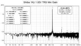
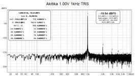
I used the Akitika and the ShibaSoku generators and got similar results. I double verified the output voltages of each generator with a DMM and the oscilloscope, which agree very well even at 1kHz.
I'm still digesting those results, but here they are for public scrutiny. At first glance... the line input for a 1Vrms input seems... better... but which is more "accurate" ... I dunno? In every other piece of laboratory work I've done, I've always had a reference test method that was known / verified / good along with reference standards for calibration. So, I'm flying a bit blind. It's fun as hell, but I'm probably going to fly into a mountain at some point.

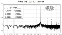
Where I am completely and totally lost is why the dBFS is roughly 6 (-14 vs -8) different between the Shiba and the Akitika when using the 'exact' same voltage output, and the exact same cabling using the XLR (mic input) with one exception. The Shiba output is BNC to RCA, but that is true also for the TRS input.
1/2 the voltage is 'seen' by the Focusrite when connecting the Akitika vs. the Shiba when using the XLR connection. I assume the difference in XLR vs. TRS is the gain change when the Focusrite detects the different connector and switches from mic to line.
I am baffled... I repeated this a few times, but that doesn't mean I did it properly.
I may get a Behringer to try... I am

Attachments

Last edited:
Shiba can be switched between SE and balanced. During the measurements it was set to SE (unbalanced). Inverted phase outputs are covered.
I should have been more clear perhaps also re: cabling.
From the Shiba...
From the Akitika
I should have been more clear perhaps also re: cabling.
From the Shiba...
BNC to RCA. RCA to XLR (with hot pin 2 and pins 1 and 3 shorted) cable. XLR (mic input) into Focusrite. Quadruple verified 1.00V between pin 2 and the 1/3 combo.
BNC to RCA. RCA to TRS cable TRS (line input, but exactly the same 'input') for the Focusrite. This agrees with the Akitika measurement.
From the Akitika
RCA to XLR (with hot pin 2 and pins 1 and 3 shorted) cable. XLR (mic input) into Focusrite. Quadruple verified 1.00V between pins 2 and the 1/3 combo. Same cabling as the Shiba minus the BNC to RCA.
RCA to TRS cable. TRS (line input, but exactly the same 'input') for the Focusrite. This agrees with the Shiba measurement.
I checked my cal file for REW and confirmed that 0dbv (I prefer dbv) is 1v RMS.
The UAC performance is totally adequate for my testing - not interested in totally inaudible by a factor of 10 or 100, harmonics and THD.
Max output of the UAC is+2dbv = 1.26v RMS - more than enough to drive all my poweramps to full output.
Of course an attenuator on the amps output is needed to drop the UAC input signal to less than 1.26 RMS.
Attachments
This is me shooting in the dark again b/c of my ignorance...
Would the output impedance of the ShibaSoku (still learning about this... still baffled)... along with the different input impedance of the Focusrite have a meaningful impact?
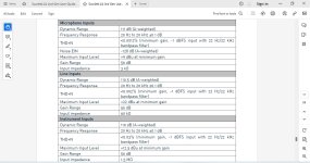
The Focusrite manual states that the input impedance for the mic input (XLR) is 3kohms. While the input impedance for the line input is 60kohms.
I truly appreciate all the help...
Would the output impedance of the ShibaSoku (still learning about this... still baffled)... along with the different input impedance of the Focusrite have a meaningful impact?
The Focusrite manual states that the input impedance for the mic input (XLR) is 3kohms. While the input impedance for the line input is 60kohms.
I truly appreciate all the help...
I realize that... completely noted with thanks. Your comment was/is why I'm switching. Many others have said to use the mic input. Their reasons seemed valid.
All I'm trying to do now is gain an understanding and set things up as properly as I can.
With that said...
The 'mic input' should not show different results with the same input voltage. Yes, it may be irrelevant if / when I stop using it, but I would really and truly like to understand it.
All I'm trying to do now is gain an understanding and set things up as properly as I can.
With that said...
The 'mic input' should not show different results with the same input voltage. Yes, it may be irrelevant if / when I stop using it, but I would really and truly like to understand it.
The UAC only has line in and outs and works for me. All I need to do is to use a dummy load (7.3r) and attenuate the signal. Simples, so not sure why you are tying yourself in knots. (I did find the Presonus more trouble getting the control set rght but always used the line input.)
^ No question there... and as said I truly, truly appreciate the input.
I just have this innate horrible terrible attribute of wanting to understand what I've F'ed up.
I truly wish I'd started with something like the QA403 that seems easy to use / plug and play. I'm going that route anyway once it arrives.
However, as frustrated as I've been... I've learned a lot through screwing things up. I just can't wrap my brain around some of it.
If I can grasp why a measured signal from two devices at the point of input of the Focusrite using the same cabling displays differently in one situation, but not another. I'll be a happy camper.
I already (think I) have a usable set up with repeatable results. I tie myself in knots trying to understand how everything interacts. In a previous life people misinterpreted test results frequently because all they saw was numbers on a page. I suppose I'd like to learn more.
I'm new to all this...
This is nothing but your assumption. And it does not hold true. A mic input, set to minimum gain for maximum input always produces magnitudes of order higher noise than an adequate line-in. The mic input is optimized for small signals at high gain. line input is optimized for large signals and low gain.With that said...
The 'mic input' should not show different results with the same input voltage. Yes, it may be irrelevant if / when I stop using it, but I would really and truly like to understand it.
^ What might be a likely cause for two signals each measuring 1.00Vrms (using two different methods to verify that they're 1.00Vrms) to display as different signal amplitudes (one 2x the other) when using the same cabling and the same input?
It may be an assumption, but it's backed at least by a few measurements... so, it borders on at least a likelihood.
I'm already agreed on the usage of the line input vs. mic input, and the noise.
I appreciate all the help!
It may be an assumption, but it's backed at least by a few measurements... so, it borders on at least a likelihood.
I'm already agreed on the usage of the line input vs. mic input, and the noise.
I appreciate all the help!
Patrick,
The Focusrite microphone input and line input gain levels at minimum adjusted input level are probably different, so the output level would be different. That would explain the different measured levels.
The 2i2 Gen 3 specifications also show a much lower input impedance for the microphone input - 3kOhm for microphone and 60kOhm for line. Perhaps the Shibasoku generator is more susceptible to feeding an input that is low impedance.
Looking at your FFT plots, I will try the line input in the future as it may have lower distortion in actual use when measuring distortion.
In the big picture, this type of measurement rig is extremely budget priced compared to laboratory grade instruments. It allows amateur diyers to measure their projects in a way that was not possible or practical not too long ago. For instance I have a HP3310A signal generator that I purchased as surplus years ago and it is useless for FFT analysis. Its harmonic distortion is just way too high. Yet when it was new it probably was sold for thousands of dollars. And the advancements in digital technology that allow all this to happen at a low price is incredible.
However it is a diy hack so the sweet spot needs to be found and then used for all measurements in order for results to be repeatable and comparable.
Or spend the big bucks for an Audio Precision analyzer. 🙂
Attachments

Apologies. I am confident my communication skills aren't top notch, and the last thing I want to do is waste other people's time that are probably pounding their fists wondering why I 'don't just get it'.
Guys... it's not about using the line vs. the mic input anymore. I don't need to be convinced. I tried to measure both because that's how I learn. It's not because I don't trust advice even it if that advice is opposite from equally wonderful people.
I also don't need to be convinced re: the merits of one technique over another or budget solutions etc.
I am very specifically and mightily confused over one thing and one thing only (for the moment).
Signal A - measures 1.00Vrms
Signal B - measures 1.00Vrms
Signal A when fed into the microphone input of the Focusrite set to minimum gain shows as -8dBFS in REW.
Signal B when fed into the microphone input of the Focusrite set to minimum gain shows as -14dBFS in REW.
Signal A comes from a ShibaSoku signal generator. Signal B comes from an Akitika oscillator.
Any offerings to help me understand that and that alone (for now) would be absolutely amazing.
6db difference is typical result in case a symmetrical source is injected into an asymmetrical input (or vice versa).
^ Thank you so much. I need to use some vernacular / likely incorrect terms, but if you'll bear with me ... I was using a similar thought to test a few things.
If by symmetrical we can substitute what I'd call differential and some call balanced... awesome. What I mean (even if it's not correct) is two equal and 'opposite' signals. I think it's important to explain what I mean... even if I haven't 100% grasped what I'm trying to hold onto. If I'm understanding it correctly also, there is no 0V reference / GND. The two signals are referenced to each other for the voltage differential => the ultimate signal.
If by asymmetrical, I can use SE or a signal referenced to a 0V vs. another signal... then I am following.
The ShibaSoku does have balanced outputs (by their term). However, the generator was set to the 'nonbalanced'. Also, the output for the 'negative' or 'inverted' signal was covered / not used.
To try and work with what might be your theory ... I actually thought I had verified things properly, but perhaps not.
The cabling from the ShibaSoku to the Mic input was...
BNC to RCA. RCA to XLR cable (pin 2 signal and Pins 1 and 3 tied as GND). XLR input to the Focusrite.
I measured 1.00Vrms between pin 2 and pins 1 and 3 (tied).
The cabling from the Akitika to the Mic input was identical with the exception of removing the unnecessary BNC to RCA.
I measured 1.00Vrms between pin 2 and pins 1 and 3 (tied).
I feel like I am missing something so boneheaded, but unless somehow 1/2 of the signal is getting 'lost to ground' or something equally mystical (to me) ... I am totally stumped.
I truly, truly appreciate the time.
I did mention the difference in input impedance in my earlier post. I do not know if this is a factor but you could try this experiment. Set both generators to 1V output with no load connected. Connect a 3kOhm load to the generator output and measure the voltage. Connect a 60kOhm load to the generator output and measure the voltage. Do that on both generators.
- Home
- Design & Build
- Software Tools
- How to - Distortion Measurements with REW