I don't have an autoranger, just the diy Akitika attenuator. It is manual ranging by me, but it works, and the price is right.
It sounds like your autoranger does not attenuate enough. I have tested a 20Vrms signal from an amplifier (50W @8R) using the diy Akitika attenuator. The gain control on my Focusrite always stays at 11 o'clock and only the attenuator is adjusted.
You probably won't be able to find an oscillator to clip a follower amp. I use the DIY 2022 FE to boost the oscillator signal when I test my follower amps. It has lower distortion than my amps so it is not a problem.
The way I look at it is that I am not looking to have a state of the art distortion analyzer. I just need a tool that is good enough to test my builds without breaking the bank, can be diyed, and can be relied upon to produce consistent results. Consistency is important so that I can reliably compare measurements that I made last year to measurements that I made this year and to measurements that I will make in the future.

Quick and entirely unscientific check...
- Measured output of oscillator with DMM and oscilloscope to make sure I wasn't completely nuts and under or over measuring the output of the oscillator(s).
- Set Focusrite to min gain. XLR input #1 "mic input" on the front.
- Started at 1Vrms. Altered output of oscillator until ring went from green to yellow. Somewhere between 1.28 and 1.285Vrms.
- Set Voltage back to 1Vrms. Moved gain to ~11 o'clock and tried to find point where it moved from yellow back to green. Didn't get to 9 o'clock. ... set voltage to 500mV. Got to 9. Set voltage to 250mV. Bumped back down ...
- It clips at around 185mV at 11 o'clock.
Hi Ben -
Looks like we posted at roughly the same time. I agree with the goals you stated. I'm not looking to have state of the art at all. I'm more just trying to understand what I'm measuring and the pros and cons of the way(s) I might go about measuring as I learn. My goal (as is yours) is consistency. So, one of my early goals is to learn as much as practical, so I start off 'on the right foot' and don't have to re-do everything after realizing I goofed it up. 🙂 I looked back at what I did in the early stages of using REW and the Focusrite. It was fun, but it was fundamentally (see what I did there) 🙂 flawed.
We may have reached a similar conclusion. The autoranger sets the output at 1Vrms. That's what it does.... well...
So, I may not be able to get into the 'sweet spot' of the gain for the Focusrite.
All the input (and your patience to teach) is truly very, very much appreciated.
Yes, it doe take time to get up to speed. I didn't know what I was doing when I first started out, and there is still a lot that I don't know. The important thing is to keep on learning.
I should note that the 11 o'clock gain position is something that I read somewhere on diyAudio. I may have tried various gain positions in the past but I do not remember the results. That is something that you can experiment with and determine for yourself. As for the autoranger not allowing you to do that, build the Akitika attenuator. It's just a rotary switch and some resistors. The LED over-voltage indicator is not really necessary.
I should note that the 11 o'clock gain position is something that I read somewhere on diyAudio. I may have tried various gain positions in the past but I do not remember the results. That is something that you can experiment with and determine for yourself. As for the autoranger not allowing you to do that, build the Akitika attenuator. It's just a rotary switch and some resistors. The LED over-voltage indicator is not really necessary.
^ Sorry for the delay. Had to do non-audio things. LOL!
I built the Akitika last night. It seems to work pretty well. I'll post some photos of the three things that I'm fooling with re: signal generators to see if I'm 1) capturing the information properly and 2) understanding and interpreting what I'm capturing in a meaningful way.
I don't have the autoranger built yet. Waiting on a few parts.
Thanks again!
Hello friends, sorry for my noobitudeness, but yes, that moment has come for me for an audio analyzer. Digged various forum, I stumbled upon this.
Basically I understood how the Rew software works, so I'd like to ask you a couple of questions more:
-can I do spectrum plots (actually V over freq.) for the dut (actually my diy'ed tube amps) ? (Here looks like I see only distortion plots on attached pictures)
- what's at the moment a convenient sound interface? (Will use my laptop)
- what's the akitika you're lately talking about? A diy sound interface?
EDIT: I saw it is an 1khz oscillator with lowest distortion. Ok. Do I really need that? Dont I need just my rigol signal generator?
- will I need a dB stepped attenuator?
Sorry for being a noob, but all in all what I need is a spectrum and distortion analyzer.
Thank you all!
Last edited:
I just realized after re-reading ...build the Akitika attenuator. It's just a rotary switch and some resistors. The LED over-voltage indicator is not really necessary.
I built that a week or so ago. I posted some pics, I think. I built the oscillator the other night. 🙂
Too many Akitikas.
As we sometimes say ... hold my beer...Hello friends, sorry for my noobitudeness,
Loosely meaning... I'm noobier than you. 🙂
I'll try to answer a few based on the help I've received from experts to save them some typing.
I'm not sure. The experts will need to chime in on that.Basically I understood how the Rew software works, so I'd like to ask you a couple of questions more:
-can I do spectrum plots (actually V over freq.)
A common DAC / ADC sound interface is a Focusrite Scarlett. There are many, but that one is often discussed.- what's at the moment a convenient sound interface? (Will use my laptop)
There is the oscillator and the attenuator. If you have a suitable signal generator, then no, you don't need another.- what's the akitika you're lately talking about? A diy sound interface?
EDIT: I saw it is an 1khz oscillator with lowest distortion. Ok. Do I really need that? Dont I need just my rigol signal generator?
Most likely. That will also depend on the choice of your sound interface. Sometimes inputting too high a voltage into a sound interface will damage it irreparably. Also, some sound interfaces seem to have a 'sweet spot' in their gain for distortion. So, it's nice to feed it a signal with a voltage allowing the gain to be close to that sweet spot if practical. A good and easy one of those is the Akitika attenuator.- will I need a dB stepped attenuator?
https://www.akitika.com/documents/BuildingTheAttenuatorRev4.pdf
Edited to add - The REW software also has a signal generator. Dare I say.... an external generator isn't even strictly necessary.
The experts have final voice, but that's what I think I've learned (so far).
Last edited:
Yes! That attenuator article is just what I've been looking for to dumb down the logic of protecting the interface. Don't know how I've missed that.
Hello friends, sorry for my noobitudeness,
We're the Three Anoobos!As we sometimes say ... hold my beer...
Loosely meaning... I'm noobier than you.
^ 
It's a wonderful little project. I think Claas posted about it early on in the thread, and I forgot about it. Ben kindly reminded me of the option a weekish ago.
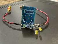
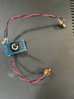
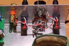
Mine is <cough> not quite to the standards of the original builders', but it's quite functional. I didn't have two resistors exactly in the 1:2 ratio... so I used two in series for the "2" part. I was impatient and was not about to wait for a Mouser order. Ideal, no... functional and quick to get me over the hump... yep. I used a left over 'twister board' to remove some of the point to point soldering.
It's a wonderful little project. I think Claas posted about it early on in the thread, and I forgot about it. Ben kindly reminded me of the option a weekish ago.
Mine is <cough> not quite to the standards of the original builders', but it's quite functional. I didn't have two resistors exactly in the 1:2 ratio... so I used two in series for the "2" part. I was impatient and was not about to wait for a Mouser order. Ideal, no... functional and quick to get me over the hump... yep. I used a left over 'twister board' to remove some of the point to point soldering.
Attachments
Last edited:
I built an Akitika attenuator, too, and I housed it in an aluminum box similar to that shown in the PDF. By chance, I discovered that if I place the attenuator box on top of my Focusrite Scarlett case during measurements, the small spikes frequently seen in the FFTs disappear.
So, it might be worth placing the attenuator parts in a metal case.
So, it might be worth placing the attenuator parts in a metal case.
^ Definitely. I was hoping it would fit into the box in the pic attached, but ... I did not plan ahead, and my build is slightly too large. Looking around for something else suitable. I don't want anyone to think that I'm totally sold on using only the autoranger. Still looking at any and all options for the most enjoyment / knob twirling.
It is interesting that having the box on top of the Focusrite (vs. on the side etc.) reduces the spikes. Curiouser and curiouser. 🙂
It is interesting that having the box on top of the Focusrite (vs. on the side etc.) reduces the spikes. Curiouser and curiouser. 🙂
Attachments

Costco sells shortbread cookies in a round metal "tin" with tight fitting lid. And I think Containers And More sells a telescoping stack of those kinds of tins, each one fitting nicely inside the next larger tin.
I think the placing the box on the Focusrite (metal to metal) grounds the shielding around the attenuator.
^ Those are things I would never have considered... Thank you for explaining.
I hadn't really tested the attenuator, so I started with what may be a typical 2V83 out from a signal generator I'm trying to learn to use. I wanted the signal generator to represent an amplifier at 1W @ 8R. I ran the output of the generator to the "in" of the attenuator, and then I checked the output of the attenuator on the scope. Everything seems to track, but the initial voltage at -6dB is a tad lower than expected. However, the multiples to follow are in-line with expectations.
1st click (-6dB) - 1V33 out
2nd click (-12dB) - 680mV out
3rd click (-18dB) - 342mV out
4th click (-24dB) - 173mV out
5th click (-30dB) - 88mV out
6th click (-36dB) - 44mV out
Then... I made an attempt to see how the attenuation might affect the distortion... I don't think I did it properly.
There is still something very wrong with my assumptions and/or my setup. I'll post more once I dig in more to see what I've either done wrong from a setup POV and/or an understanding what I'm seeing visually POV.
I 'ran the gauntlet' at my local Costco yesterday... I'm loathe to return soon, but shortbreads and a project box combo is strong incentive. 🙂Costco sells shortbread cookies in a round metal "tin" with tight fitting lid. And I think Containers And More sells a telescoping stack of those kinds of tins, each one fitting nicely inside the next larger tin.
I hadn't really tested the attenuator, so I started with what may be a typical 2V83 out from a signal generator I'm trying to learn to use. I wanted the signal generator to represent an amplifier at 1W @ 8R. I ran the output of the generator to the "in" of the attenuator, and then I checked the output of the attenuator on the scope. Everything seems to track, but the initial voltage at -6dB is a tad lower than expected. However, the multiples to follow are in-line with expectations.
1st click (-6dB) - 1V33 out
2nd click (-12dB) - 680mV out
3rd click (-18dB) - 342mV out
4th click (-24dB) - 173mV out
5th click (-30dB) - 88mV out
6th click (-36dB) - 44mV out
Then... I made an attempt to see how the attenuation might affect the distortion... I don't think I did it properly.
There is still something very wrong with my assumptions and/or my setup. I'll post more once I dig in more to see what I've either done wrong from a setup POV and/or an understanding what I'm seeing visually POV.
The -6dB is close. -6dB is a ratio of 0.501, times 2.83V equals 1.42V.
As for measuring distortion, I usually try to set the attenuator so that REW sees the signal somewhere between -10dBFS and -20dBFS. Below -10dBFS, especially if it gets close to -3dBFS, the Focusrite gets overloaded.
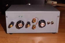
I put my Victor oscillator, its power supply, and the Akitika all in one chassis. I cut up a tin can to shield the power transformer and I added a piece of Mu-metal to shield the attenuator and oscillator from the transformer.
On the front panel, from left to right, is the attenuator output, attenuator rotary switch, attenuator input for connection to DUT, with a choice of RCA or individual signal + and - terminals, oscillator signal level adjustment, and two oscillator output RCAs. The attenuator input + and - terminals are handy for connecting a load resistor if the DUT is a preamp, and the terminals can also be used to attach a Volt meter to measure DUT output Voltage.
I chose a linear power supply because I didn't want to deal with replacing batteries.
For power amplifier testing, the load resistors are on a heat sink, and the output wires are terminated with a RCA plug for easy connection to the attenuator.
As for measuring distortion, I usually try to set the attenuator so that REW sees the signal somewhere between -10dBFS and -20dBFS. Below -10dBFS, especially if it gets close to -3dBFS, the Focusrite gets overloaded.
I put my Victor oscillator, its power supply, and the Akitika all in one chassis. I cut up a tin can to shield the power transformer and I added a piece of Mu-metal to shield the attenuator and oscillator from the transformer.
On the front panel, from left to right, is the attenuator output, attenuator rotary switch, attenuator input for connection to DUT, with a choice of RCA or individual signal + and - terminals, oscillator signal level adjustment, and two oscillator output RCAs. The attenuator input + and - terminals are handy for connecting a load resistor if the DUT is a preamp, and the terminals can also be used to attach a Volt meter to measure DUT output Voltage.
I chose a linear power supply because I didn't want to deal with replacing batteries.
For power amplifier testing, the load resistors are on a heat sink, and the output wires are terminated with a RCA plug for easy connection to the attenuator.
Attachments
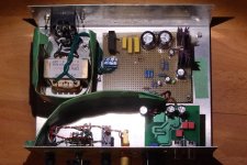

I can't make out the make/model of those 50W load resistors , but some caution may be needed to confirm they don't have substantial TCR or distortion. I had one make/model (RS branded) which exhibited a large TCR which I think was due to a different type of metal end terminal - whereas an Arcol HS50 was blameless. There are also some threads on determining the distortion from load resistors - which can be a concern when trying to measure quite low levels of harmonics.
^ Great information. I'll have to look that up also. I got Arcol NHS 1% 'low-inductive' types for higher wattage testing. So, hopefully... 
@Ben Mah - thank you for the pictures and the descriptions. I feel like I started this hobby 'in reverse'. I started with beautiful PCBs, kits, and well-written guides. I'm just now starting to cobble things together with a bit of ingenuity and my limited knowledge. That part is a ton of fun, and unsurprisingly very rewarding when I get it right... and even when I get it wrong.
@Ben Mah - thank you for the pictures and the descriptions. I feel like I started this hobby 'in reverse'. I started with beautiful PCBs, kits, and well-written guides. I'm just now starting to cobble things together with a bit of ingenuity and my limited knowledge. That part is a ton of fun, and unsurprisingly very rewarding when I get it right... and even when I get it wrong.
I used REW to measure a cheap EL34 amp that I improved. Ialso checked my Krell KSA50 clone and Quad 306.Hello friends, sorry for my noobitudeness, but yes, that moment has come for me for an audio analyzer. Digged various forum, I stumbled upon this.
Basically I understood how the Rew software works, so I'd like to ask you a couple of questions more:
-can I do spectrum plots (actually V over freq.) for the dut (actually my diy'ed tube amps) ? (Here looks like I see only distortion plots on attached pictures)
- what's at the moment a convenient sound interface? (Will use my laptop)
- what's the akitika you're lately talking about? A diy sound interface?
EDIT: I saw it is an 1khz oscillator with lowest distortion. Ok. Do I really need that? Dont I need just my rigol signal generator?
- will I need a dB stepped attenuator?
Sorry for being a noob, but all in all what I need is a spectrum and distortion analyzer.
Thank you all!
I used Picoscope to check at higher levels.
The interface is a Behringer UAC222 £25 and works well. Input impedance is 27k, and levels are 2dbv in and out. No need for anything more costly and no drivers needed for Win 10/11.
https://www.diyaudio.com/community/...e-unusual-topology.401911/page-4#post-7432301
PS you shouldn't use a MIC input for measuring line levels.
I also have a Presonus Audio Box One and find the UAC is far less hassle but I did make a 20:! attenuator when connecting to the speaker outputs. I needto make bigger attenuator as REW doesn't like 8v RMS,hence I use Picoscope which has a +-20v p-p max input.
- Home
- Design & Build
- Software Tools
- How to - Distortion Measurements with REW