Yes, I drew that earlier. All on the same page. Truly appreciate one more confirmation.What pinholer said. When the switch is off the output impedance is 600R. When the switch is on, a 600R is added across the output.
That's the observation I mentioned a number of times. However, I admit to struggling with your use of the word "correct". I suppose that's proper because all we're really interested in is the voltage across the load... I'd think. The "originating" voltage or Vs is important, but not nearly as important as the voltage across the load. Still pondering... I admit.So the output voltage displayed is only correct when the switch is on, with 600R across the output.
Agreed 100%. I'm glad I always follow that practice. It's what got us into this conversation. 🙂 A lot of my calculations would have been way off. It's also why I measure everything without a display.When the switch is off, the output voltage is twice the displayed voltage. That is a good reason to measure the output voltage rather than trust the voltage displayed on the generator's meter.
Agreed, but it took us a minute to arrive here. Many thought that the output impedance was high(er). I believe you did. So, I tested. It's fun.The output impedance is low enough that the input impedance of the Focusrite is not an issue.
Agreed. That's why I measured it too. I wanted to see how it compared. It turns out to be the... culprit. Even though it behaved exactly as the designer said it would. (Minus the fact that I get 2x maximum voltage output).The Akitika's output impedance being much higher would affect the output voltage of the Focusrite, and that is shown in the difference between the TRS and XLR FFTs.

I copied and pasted a lot of your explanations into my notes. This one... I'll come back to ... later. I've already polluted this thread enough.The practical use is so the input voltage to a DUT stays fairly constant with frequency even though the DUT's input impedance varies with frequency.
I think I have a rudimentary understanding. The practical understanding / usage is... keep the darn light on. 🙂
My sincerest of thanks to you and to everyone... batteryman, bucks, Ben, and I'm sure I've left out a few.... but thanks!

We were on the right track, assuming an impedance issue, but without voltage measurements with and without resistor loads, it was all guessing. There were many variables - input impedance of Focusrite TRS and XLR, output impedance of generators, and the function of the Shiba switch. Trouble shooting can take several steps, with the gathering of information at each step.
^ I'm sure it was agonizing for many to read (or skip over). 
Agreed! More information was needed, and I just couldn't leave well enough alone. I loved the sharing of the ideas re: what it could have been and turned out to be. If you don't have a hypothesis to test... you're shooting into the wind. So, I appreciated the ideas, and I wanted to put in the effort to to test each idea that someone was kind enough to put out there. Also, I couldn't grasp why the Shiba would show a higher relative voltage (-8 dBFS) than the Akitika (-14dBFS) with the same settings, same wiring, and same Zin for the Fosusrite if the Shiba's Zout was higher than the Akitika. That didn't make sense to me. It was truly fun.
Sure, I could have just used the line inputs, and not worried about it, but I had to try to understand ... why? The measurements I took this morning over a few coffees reminded me of school labs. I had a bit of nostalgic fun learning new things, and I considered it a good use of time. I won't forget the basics I picked up or the kindness of the people that agonized through the walls of text to help an old dog learn a new trick.
As I continue to fiddle around with REW and other software to learn some of the basics, I observed something interesting (to me), Per the norm, it may not be interesting to others or even apply.
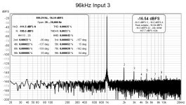
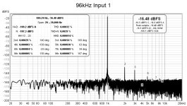
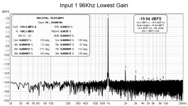
With a Focusrite Scarlett 4i4 Gen 3, REW, and a few oscillators, I found that the displayed phase of the harmonic distortion varies with the physical input used on the Focusrite. In my observations, inputs 1 and 2 display similarly. Inputs 3 and 4 display similarly. Group 1&2 vs group 3&4 display differently. When using input 1, the gain was adjusted to minimum and also set to match the level of input 3. This was done to check if the amplifier/attenuation in the Focusrite was altering the phase. It doesn't seem to have an effect. I haven't the foggiest, which is correct/accurate. I do know if I blindly trusted the numbers displayed that I'd draw incorrect conclusions in one or both situations. Until I find a way to run a known control... I won't know.
YMMV... As clearly demonstrated, I am new to all of this, but if you happen to be using a Focusrite with both front and rear inputs, you may want to check your measurements.
Two examples from the ShibaSoku oscillator at 1kHz 1Vrms output. Gain of input 1 adjusted and unadjusted. Input 3. All "line" inputs. All TRS input.
As I learn more about timing / sampling of a continuously varying analog signal... I assume that the phase is calculated by the relative voltage at the same "instant", but again... I haven't a clue. I changed sampling frequency to see if that had an effect. It did not as far as I could tell.
Note - just to be absolutely certain, I ran a calibration for both input 1 and input 3. Measurements were taken with Input 1 calibrated and Input 3 calibrated. No meaningful difference. Pics attached were from Input 1 calibrated.
I still may have done something totally incorrectly. My goal is to be able to produce repeatable and hopefully accurate measurements. Repeatability has improved significantly to the point where n=2 is likely okay for many measurements for my purposes. Accuracy is nowhere near verified. I couldn't say with any confidence what the phase of the distortion relative to the fundamental is.
More fun stuff to learn...
Attachments
I have a 2i2 Gen 2. I always use the same oscillator, the same 2i2 input, the same 2i2 gain setting, the same REW settings every time I do measurements. That has worked for me to get repeatable results. Whether they are accurate in absolute values, I do not know as I do not have a laboratory grade distortion analyzer to verify the results. But the results seem reasonable.
^ Hi Ben 🙂
No question. I've never once questioned your methodology or your goals.
As far as I know, a 2i2 only has one set of inputs on the front vs. front and rear...
Mostly, I like to understand what I'm measuring and how it's measured and recorded. REW has the feature, and I'd like to use it. I'd also like to know if the reported change in phase is because of the software and/or the hardware.
As always, I welcome more information.
With thanks as always for chiming in. It is truly appreciated.
No question. I've never once questioned your methodology or your goals.
As far as I know, a 2i2 only has one set of inputs on the front vs. front and rear...
Why, you may ask might I want to use front vs. rear or both? The front inputs on my unit have a variable gain; the rears do not. There are times where variable gain could be a plus, and some times it may be a hindrance. I wanted to figure out if there was a difference in how they measured, so I could potentially take advantage of both. Believe me, I know how to minimize variables in a certified laboratory testing environment, but I was/am willing to introduce a variable... IF the benefits outweighed the costs. In this case they don't. It was also just an FYI for others that may have similar units. They may also care. I know it's not applicable in your use case. No worries.but if you happen to be using a Focusrite with both front and rear inputs,
Mostly, I like to understand what I'm measuring and how it's measured and recorded. REW has the feature, and I'd like to use it. I'd also like to know if the reported change in phase is because of the software and/or the hardware.
As always, I welcome more information.
With thanks as always for chiming in. It is truly appreciated.
Hi All,
I have just started using REW to measure my DIY audio amlpifier designs - Really great software but I am having one problem.
I have REW installed of two PCs a Desktop and a Laptop. Works just fine on the Desktop.
However, on the laptop, when I increase the level of the signal on the generator to over 207mV it is regularly resetting ( swtching off ) with an error message saying that the SPL is too high.
I have calibrated the generator with the external sound card ( Xonar U7) line output so that part is OK.
I need to generate about 300mV to get the desired test level on the amplifier.
The initial test O/P of the amp ( 5v peak ) is attenuated down to 0.455V with a 1k / 100 ohm divider before being fed into the line input of the sound card ( well within the limits of the soundcard line input )
So on the face of it there is no reason for the generator to be automatically reset - but yet it is resetting repeatedly.
If someone can pont me in the right direction to fix this problem, that would be great.
Many thanks
mike mears
Is this because the input from the amp is too high?
My Behringer UAC222 should have 2v rms in and out capability but REW seems not to want to use the full range of it's input even though I have run the cal process.
I have used a 10:1 attenuator which should mean 20v RMS but have had to switch to a poteniometer so I can adjust the input so I can reach max output of my EL34 amp of about 9v rms.
Recent measurements: https://www.diyaudio.com/community/threads/x10-clone-tube-buffer-with-6n1p.402747/#post-7439570
One thing I have noticed with REW and my audio interface is that it cannot be used with square waves as there is massive ringing (due to limited bandwidth somone said).
Instead I use a battery powered sig gen (Tenma) and Picoscope for these tests.
Last edited:
I asked the same question over in the REW forum too and John Mulcahy came back within 15 minutes with the answer which is this:
"Just uncheck this box on the generator:

If you wanted to use an SPL limit (or measure SPL) at some point then go through the SPL meter SPL calibration."
I'll comfirm the fix tomorrow when I try it.
"Just uncheck this box on the generator:
If you wanted to use an SPL limit (or measure SPL) at some point then go through the SPL meter SPL calibration."
I'll comfirm the fix tomorrow when I try it.
Last edited:
Hello,
I have a general question.
I currently have a Tascam US-1x2 (older model) that I use with REW and others softwares on W10.
If it had to be changed, would you take the Tascam US-1x2HR or the Focusrite Scarlett 2i2?
Personally, I like the Tascam with these two RCAs on the back.
Regards,
Stéphane
I have a general question.
I currently have a Tascam US-1x2 (older model) that I use with REW and others softwares on W10.
If it had to be changed, would you take the Tascam US-1x2HR or the Focusrite Scarlett 2i2?
Personally, I like the Tascam with these two RCAs on the back.
Regards,
Stéphane
I have not used the Tascam so can’t comment on what’s better. I do know that the Focusrite was quieter than the Behringer. Although latter was a budget $40 vs $150 Focusrite. It comes down to what you can live with and how easy it is to connect and lastly, it’s low level of self distortion.
Hi All,
When using REW to test my DIY Class A mono block power amps I have noticed some anomolies.
I tested both amps in last few days and at 1.5 watts only 2nd & 3rd Harmonics were present. All other harmonics were below the noise floor in the -125 to -130db region.
However, when testing the same amps, unchanged, today with similar settings I am seeing various harmonics like 7th of 9th ( most undesirable ) at around -100db
I tried many different settings to no effect until I accidently changed the frequency to 1001hz. At this frequency all higher harmonics fell back down into the noise floor.
After trying various frequencies like 500 1k 2k 3k 4k 5k these harmonics like 7 & 9 are once again at a higher level . . .
BUT when I tried changing the frequencies by one digit either up or down i.e. 1999hz or 2001hz, the higher harmonics consistantly fell back into the noise floor.
Logic would suggest that this is some kind of a digit anomaly. I cannot imagine my amp's HD signatures are changing so much with a 1hz difference.
So my question is this: Are the rounded frequencies, 1k 2k etc somehow engineered to be more accurate or . . . .
Could there be some kind of digital anomaly being created with these exact frequencies which is not present with the slightly offset frequencies ?
I would really like to know which measurements are most accurate
BTW I did try 5001 5002 5003 5004 5005Hz and at all these values the higher harmonics were consistantly within in the noise floor.
Many thanks
mike mears
There are many ways to generate any tone at any frequency, samplerate, bit width, channel count, sox being one of the most flexible ones. For USB I would try to avoid the exactly 1kHz as many USB devices experience 1kHz artefacts due to the USB transport.
Sure . . . . After establishing that I was not applying differ on the generator, this was John's advice:
"Digital signals need to be dithered to prevent quantisation causing artefacts in the spectrum. The dither should be set to the bit depth of the signal, so a 16-bit output should use 16-bit dither.
The worst signals for generating artefacts are those with a small number of repeating samples. A 1 kHz signal at 48 kHz sample rate has only 48 unique sample values, a small change in frequency produces a signal with many more different sample values which introduces a degree of self-dithering, but dither is the best solution.
With the Java drivers on Windows choose device names that start with EXCL, that will use a WASAPI Exclusive driver and provide the full bit depth the interface supports."
Following this has fixed the problem

If you check the signals on this Denon tech CD you will see that its a known aspect..
https://www.discogs.com/release/5794742-No-Artist-Denon-Audio-Technical-CD
//
https://www.discogs.com/release/5794742-No-Artist-Denon-Audio-Technical-CD
//
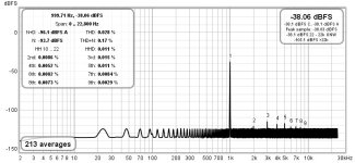
Your right hand plot seems to use 16-bit Java driver. Only WASAPI Exclusive Java driver in REW is 32-bit.has anyone noticed a difference between using the Java driver against the Asio driver? I get different measurements using each one, see attached pics. Which one would you go off?
- Home
- Design & Build
- Software Tools
- How to - Distortion Measurements with REW