That 2 way design from @fluid is a classic, solid and easy to build.
I have a suggestion, considering the mk32b2 is a wide horn that has excellent directivity and loading down to 400Hz. I can't drive VCAD but I can show the effect using Hornresp. I used the same driver, rear chamber volume and port dimensions in Hornresp and got the exact same tuning to use as the baseline. I've assumed the 120L internal dimensions are H55xW62xD35.
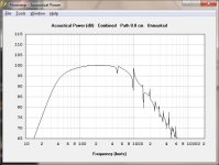
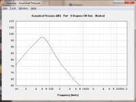
Pic1 is the BR (direct radiator + port) power response (function of SPL and beamwidth) unmasked, showing internal reflections that will radiate via the driver cone. A small amount of safe damping material will eliminate this. All other graphs will be masked to hide this
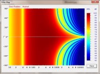
Pic2 is the polar of a direct radiator showing the beaming pattern and side lobes at higher freq.
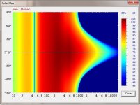
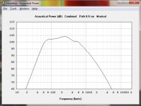
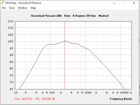
Pic3 is the power response of a shallow HypEx horn 15cm deep built into the box. The overall box dimensions are still the same H55xW62xD35, but the cost is reduced internal chamber to 80L which means higher tuning. This is a ported HypEx horn that has minimal horn gain (some at 250Hz) with much better directivity control at lower freq and no side lobes w.r.t direct radiator. The horn could be built with flat walls. It will be very easy compared to the mk32b2 horn.
Pic4 shows the polar response of the shallow HypEx horn. The larger mouth controls beamwidth better at lower freq and beams more gradually.
Pic5 shows the SPL beamwidth comparison between the direct radiator and shallow horn.
The shallow horn with reduced rear chamber (80L vs 120L) does not go as low but you may be able to compensate with either 1) placement (near wall) or 2) DSP Eq or 3) subwoofer or 4) bigger box. The Hornresp files are included.
I have a suggestion, considering the mk32b2 is a wide horn that has excellent directivity and loading down to 400Hz. I can't drive VCAD but I can show the effect using Hornresp. I used the same driver, rear chamber volume and port dimensions in Hornresp and got the exact same tuning to use as the baseline. I've assumed the 120L internal dimensions are H55xW62xD35.
Pic1 is the BR (direct radiator + port) power response (function of SPL and beamwidth) unmasked, showing internal reflections that will radiate via the driver cone. A small amount of safe damping material will eliminate this. All other graphs will be masked to hide this
Pic2 is the polar of a direct radiator showing the beaming pattern and side lobes at higher freq.
Pic3 is the power response of a shallow HypEx horn 15cm deep built into the box. The overall box dimensions are still the same H55xW62xD35, but the cost is reduced internal chamber to 80L which means higher tuning. This is a ported HypEx horn that has minimal horn gain (some at 250Hz) with much better directivity control at lower freq and no side lobes w.r.t direct radiator. The horn could be built with flat walls. It will be very easy compared to the mk32b2 horn.
Pic4 shows the polar response of the shallow HypEx horn. The larger mouth controls beamwidth better at lower freq and beams more gradually.
Pic5 shows the SPL beamwidth comparison between the direct radiator and shallow horn.
The shallow horn with reduced rear chamber (80L vs 120L) does not go as low but you may be able to compensate with either 1) placement (near wall) or 2) DSP Eq or 3) subwoofer or 4) bigger box. The Hornresp files are included.
Attachments
-
 Pic1-BR-Direct-Unmasked-Pwr.jpg53.9 KB · Views: 84
 -
 Pic2-BR-direct-polar.jpg60 KB · Views: 86
 -
 Pic3-BR-Horn-Masked-Pwr.jpg53 KB · Views: 88
 -
 Pic4-ShallowHorn-polar.jpg49.6 KB · Views: 88
 -
 Pic5-Beamwidth Direct vs ShallowHorn.jpg47.3 KB · Views: 92
 -
FP-15PR400-BR.txt2.7 KB · Views: 76
-
FP-15PR400-BRhrn.txt2.7 KB · Views: 73
Last edited:

The 15" woofer will be more like 110 degrees at 800Hz, like is shown in the Hornresp graph. Don's short horn or something like it would help to smooth the directivity match and maintain the directivity lower. There will still be a reasonable match without it though and the crossover can help fudge it.Since the horn has 90+ degrees beam width around 600-800Hz region and 15inch woofer beamwidth becomes 90 degrees around 800Hz, the intended crossover is somewhere between 600 to 800 Hz.
Thanks for this, you have me mighty interested!Pic3 is the power response of a shallow HypEx horn 15cm deep built into the box. The overall box dimensions are still the same H55xW62xD35, but the cost is reduced internal chamber to 80L which means higher tuning. This is a ported HypEx horn that has minimal horn gain (some at 250Hz) with much better directivity control at lower freq and no side lobes w.r.t direct radiator. The horn could be built with flat walls. It will be very easy compared to the mk32b2 horn.
@DonVK & @fluid: Thanks for these suggestions. We are very interested in the short horn for the bass cabinet.
But I don't have much experience about how to design using hornresp or even translate the horn resp file into the horn design in a software like fusion 360.
Can you please point me to any resources about this where I can read up and start using the hornresp project that you have given?
The cabinet dimensions for bass reflex was not fixed earlier but we were aiming for a box width of around 64cm & depth less than 40cm. So it has to be fixed now based on the new design & required volume.
Also, to make sure that I understand the idea of the short horn, will it be something like you have used in your project?

Another example that I could think of is one from Joseph Crowe shown here:
https://josephcrowe.com/products/speaker-system-no-2087

The difference in our case being that the horn profile will be as per a hyperbolic exponential profile for the front and a regular bass reflex box of desired volume behind it?
But I don't have much experience about how to design using hornresp or even translate the horn resp file into the horn design in a software like fusion 360.
Can you please point me to any resources about this where I can read up and start using the hornresp project that you have given?
The cabinet dimensions for bass reflex was not fixed earlier but we were aiming for a box width of around 64cm & depth less than 40cm. So it has to be fixed now based on the new design & required volume.
Also, to make sure that I understand the idea of the short horn, will it be something like you have used in your project?
Another example that I could think of is one from Joseph Crowe shown here:
https://josephcrowe.com/products/speaker-system-no-2087
The difference in our case being that the horn profile will be as per a hyperbolic exponential profile for the front and a regular bass reflex box of desired volume behind it?
After the project is loaded hit calculate. Then from the File menu choose export > Horn Data that will save a text file with all the data. You can make a spline out of the length and Radius colums by importing them into excel and filling a third colum with zeros and saving as a csv.Can you please point me to any resources about this where I can read up and start using the hornresp project that you have given?
There is a default script in Fusion to create a spline from a csv. The three colums represent x,yand z, so you can change the orientaion of the spline by the order of the colums or move around afterwards.
Then sweep the spline around a circle sketch made at the throat that coincides with the first point. If you want the horn to be round.
Last edited:
There is also the Hypex approximater that will let you use conical, parabolic or exponentail sections or just tweak however many different sections you want the horn to be made out of. S1 to S2 is one section S2 to S3 another, they represent areas with either Length or other parameters that can be calculated to decide on the right length for each section.
https://www.hometheatershack.com/threads/hornresp-for-dum-hmm-everyone.36532/
https://dokumen.pub/hornresp-manual.html
and the inbuilt help file
https://www.hometheatershack.com/threads/hornresp-for-dum-hmm-everyone.36532/
https://dokumen.pub/hornresp-manual.html
and the inbuilt help file
We have got more data now.
@WetFartz was able to take some measurements of the Faital pro HF146 driver and the Rosso-65 CDN-T attached to the horn today (the horn fins were stiffened).
Here is a comparison of impedance measurements from HF146 & Rosso 65CDN-T in free air taken today

Here is a comparison of impedance measurements of Rosso 65CDN-T with & without the horn

Impedance magnitude & phase of Rosso 65CDN-T attached to horn

Here is a comparison between HF146 & Rosso 65CDN-T on horn

SPectrogram of HF146 driver

Spectrogram of Rosso driver

Here is a comparison of the on axis SPL responses of both drivers on the horn taken from 2m away (7ms gated response)

It seems like the rosso driver has more high frequency extension... 😀
Now it will be very interesting to the see the polars of the Rosso. @WetFartz told that he will work on getting it tomorrow or day after... 🙂
Exciting times.. 🙂
In the meanwhile, Thanks to @fluid 's tips, I was able to design the round horn for the bass driver. But I am trying to do some kind of round-to-square transition. Will update if I have some progress/I get stuck.. 😀
@WetFartz was able to take some measurements of the Faital pro HF146 driver and the Rosso-65 CDN-T attached to the horn today (the horn fins were stiffened).
Here is a comparison of impedance measurements from HF146 & Rosso 65CDN-T in free air taken today
Here is a comparison of impedance measurements of Rosso 65CDN-T with & without the horn
Impedance magnitude & phase of Rosso 65CDN-T attached to horn
Here is a comparison between HF146 & Rosso 65CDN-T on horn
SPectrogram of HF146 driver
Spectrogram of Rosso driver
Here is a comparison of the on axis SPL responses of both drivers on the horn taken from 2m away (7ms gated response)
It seems like the rosso driver has more high frequency extension... 😀
Now it will be very interesting to the see the polars of the Rosso. @WetFartz told that he will work on getting it tomorrow or day after... 🙂
Exciting times.. 🙂
In the meanwhile, Thanks to @fluid 's tips, I was able to design the round horn for the bass driver. But I am trying to do some kind of round-to-square transition. Will update if I have some progress/I get stuck.. 😀
Last edited:
Is the Rosso's mouth a way better fit to the adapter? It would be worth it to investigate an inset-tube for the HF146 that has a smooth transition from phase plug to the horn. It would probably need a different adapter, but maybe it can be printed as one (protruding part into the HF146 + adapter from round to square to horn) for prototyping. It's easy enough to come up with a 3D file and printing is easy. Most probably not as a final solution (as the part itself may not be resonance free) but it could be used to work out the smoothest way from 'driver phase plug-out' to 'horn entrance-in' 😉. If you have the dimensions, a more permanent solution could be made. Maybe even a cast part in a suitable material.
I'm sure you guys are familiar with the use of modeling clay by Dr. Geddes to smooth out transitions from driver to horn?
It underlines the importance he puts into the smooth transition from the driver to the horn. I'm betting it will be of influence for that HF146 driver as well.
Instead of using this method, filling up the gap smoothly from phase plug with the adapter all the way to the horn entrance should also work well. Make it a smooth transition, that's the point I'm making.
I'm sure you guys are familiar with the use of modeling clay by Dr. Geddes to smooth out transitions from driver to horn?
Source: https://www.diyaudio.com/community/threads/building-the-nathan-10.127152/page-19#post-1587305gedlee said:I do use modeling clay. It works very well. It seals the gaps and smooths the small variations quite nicely and doesn't harden. If you know that you are not going to change the driver then something more permanent might be better - like silicone or filler putty, but I am never that confident - so I use clay. It takes only a very small amount - less that a finger tip. As I said, the gap in the driver makes this a necessity, but it also fills any other voids and deviations that could be a problem. Fingers are very sensitive to small deviations. You can feel a flaw in a surface that you cannot see.
It underlines the importance he puts into the smooth transition from the driver to the horn. I'm betting it will be of influence for that HF146 driver as well.
Instead of using this method, filling up the gap smoothly from phase plug with the adapter all the way to the horn entrance should also work well. Make it a smooth transition, that's the point I'm making.
Last edited:
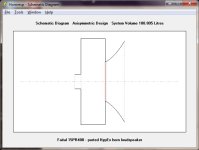
So I used @DonVK's Hornresp files & fluid's tips to create the following short horn profile for the bass cabinet.
This one is square of side = 66.7cm dimension.

Is this kind of horn needed or we only need to make the horizontal profile like Don's speaker shown below

Another doubt I got is that the above horn throat has slightly less diameter than the driver. Is it intentional?
This one is square of side = 66.7cm dimension.
Is this kind of horn needed or we only need to make the horizontal profile like Don's speaker shown below
Another doubt I got is that the above horn throat has slightly less diameter than the driver. Is it intentional?
May we see a photo of the horn throat without adapter as close up please. I would like to see how sharp the fins are at this side pointing to the driver.
@DonVK & @fluid: Thanks for these suggestions. We are very interested in the short horn for the bass cabinet.
But I don't have much experience about how to design using hornresp or even translate the horn resp file into the horn design in a software like fusion 360.
Can you please point me to any resources about this where I can read up and start using the hornresp project that you have given?
The cabinet dimensions for bass reflex was not fixed earlier but we were aiming for a box width of around 64cm & depth less than 40cm. So it has to be fixed now based on the new design & required volume.
Also, to make sure that I understand the idea of the short horn, will it be something like you have used in your project?
[snipped out - DonVK]
The difference in our case being that the horn profile will be as per a hyperbolic exponential profile for the front and a regular bass reflex box of desired volume behind it?
Yes, I use the same concept in my 3way. I made the horn as an "add on" and it can be removed. The drivers I used need little volume, and used sealed chambers. So the driver column behind the horn is skinny
The overall box dimensions are whatever you want, I just provided an example based on the VCAD volume, so feel free to adjust to your needs. There is no intended driver restriction (compression), I just used the same Sd as the driver for the throat. A short horn is not sensitive to small changes to the mouth area or length.
Hornresp can directly export many form factor variations that still conform to the design HypEx area expansion. The one @fluid provided is axisymetric, but you can make it whatever you want, including flat walls to make it easier to build.
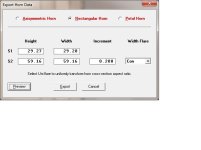
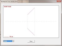
To create printable profiles from Hornresp. Run "calculate", then switch view [window]->[schematic view] (pic1), then [File]->[Export]->[Horn Data] and a pop up window appears (pic2). Next you can select the form factor of the horn you want (axisym, rectangle, peddle) and you can force one side (flare width) to be conical to force it to a flat surface. You can preview the profile (height or width) to see if its suitable (pic3). The height or width can be manually adjusted and the rest automatically recalculated. If you're happy then "export" (pic2) the data as "csv" or "txt" and let the carpentry begin. 🙂 The horn throat does not have to be round at the woofer and a small square is approximate and sufficient
[edit] @fluid also posted some instructions, this shows how to create a flat wall]
Attachments
Last edited:
I find this very interesting. What would the impact be on the crossover? How about corrections or dealing with the extra gain introduced around 250 Hz?Pic3 is the power response of a shallow HypEx horn 15cm deep built into the box.
I have been intrigued with those small horns on the Blumenhofers and these plots might hint why they are useful...
@swak The graphs were power responses, so they are a function of SPL and beamwidth.
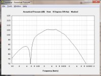
I've added on-axis SPL (pressure) curves for the driver and port separated (pic2 and pic3). Usually the on axis SPL is EQ'd ignoring the beamwidth. It looks like most of the power bump is not seen in the axial SPL. So probably no impact on the XO.
I've added on-axis SPL (pressure) curves for the driver and port separated (pic2 and pic3). Usually the on axis SPL is EQ'd ignoring the beamwidth. It looks like most of the power bump is not seen in the axial SPL. So probably no impact on the XO.
Attachments
We have got more data now.
@WetFartz was able to take some measurements of the Faital pro HF146 driver and the Rosso-65 CDN-T attached to the horn today (the horn fins were stiffened).
Here is a comparison of impedance measurements from HF146 & Rosso 65CDN-T in free air taken today
Here is a comparison of impedance measurements of Rosso 65CDN-T with & without the horn
Impedance magnitude & phase of Rosso 65CDN-T attached to horn
Here is a comparison between HF146 & Rosso 65CDN-T on horn
SPectrogram of HF146 driver
Spectrogram of Rosso driver
Here is a comparison of the on axis SPL responses of both drivers on the horn taken from 2m away (7ms gated response)
It seems like the rosso driver has more high frequency extension... 😀
Now it will be very interesting to the see the polars of the Rosso. @WetFartz told that he will work on getting it tomorrow or day after... 🙂
Exciting times.. 🙂
In the meanwhile, Thanks to @fluid 's tips, I was able to design the round horn for the bass driver. But I am trying to do some kind of round-to-square transition. Will update if I have some progress/I get stuck.. 😀
Many thanks @WetFartz , @vineethkumar01 for taking the measurements and sharing the results.
Stiffening the fins made a small measurable impedance difference for the Faital but I'm not convinced it's significant. Both drivers have their loaded impedance curve peak magnitudes lowered, spreadout and shifted down in frequency. It's interesting that (if asked) you could not identify the horn from those loaded curves because interaction with the driver is more complex (motor, diaphragm, exit angle, phase plug).
It certainly looks like the Rosso (18 deg) exit angle has more HF performance but that could also be from the titanium diaphragm.
The Faital (36deg) exit angle seems to have better LF performance, but less HF performance which could also be the poly diaphragm.
I'm wondering how frequency sensitive the exit angle mismatch is. The mismatch at 500Hz would seem less significant than 10Khz because of the wavelength.
Yes. I have a few more measurements due tomorrow with the bass bin. I'll have the horn detached and photographed soon after.May we see a photo of the horn throat without adapter as close up please. I would like to see how sharp the fins are at this side pointing to the driver.
We now have polars from the Rosso 65 CDN-T driver on mk3b2 thanks to @WetFartz spending time very early in the morning for it.. 😀
Raw measurements (from 2m away, 6.5ms gated)

Spin data created using VituixCAD (normalized polars in directivity plot)

Threw in a bit of passband linearization EQ and got results like this (reference is 20 degrees off axis) 😀


Raw measurements (from 2m away, 6.5ms gated)
Spin data created using VituixCAD (normalized polars in directivity plot)
Threw in a bit of passband linearization EQ and got results like this (reference is 20 degrees off axis) 😀
😮 how did you manage to pick out a post from 2008!
- Home
- Loudspeakers
- Multi-Way
- 2-way horn system based on the MK3B2