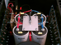
Having a pair of old Threshold amps I wonder if it is a real benefit to install solid caps (that's how ZenMod calls film caps 😉) over the big electrolytic PSU caps like this of course:

I ask this because I read an article called ´‘Power Supplies: Commentary for Consumers’, by Nelson Pass.
Excerpt about capacitors from that article:
"Big electrolytic capacitors have a small amount of inductance, or "coilness", in their makeup, a result of the spiral winding of the capacitive
film. To reduce the effect of this inductance, film capacitors which have
low inductance are often placed in parallel, so that at high frequencies
the current flows a little more easily.
An examination of the numbers will provide some insight here. It is common for the inductance of a large electrolytic capacitor to cause its
impedance to begin increasing at about 10 KHz so that its impedance is a large fraction of an ohm at 100 KHz.
Placing a film cap in parallel will keep the impedance to .1 ohm or so above this frequency.
Is this important because audio has real power at these frequencies?
No. Audio has power which declines at about 12 dB/octave above 5 Khz, and real musical slew rate figures are a fraction of a volt per
microsecond, meaning that practically no power is needed at 100 Khz.
However, high frequency impedance can be important to the stability of the amplifier, particularly with more complex circuits, as the source
impedance of the power supply starts figuring into the feedback at frequencies of a mega-Hertz or so. Interestingly, some designers have
depended on a particular source impedance of the supply at these frequencies for stability, thus it is possible to destabilize the amplifier
circuit by paralleling film capacitors across the electrolytics.
In general, however, film caps in the power supplies are a good sign from the consumer's standpoint."
Maybe I draw the wrong conclusion here but it seems that NP doesn´t recommend/finds it beneficiary to install solid caps in the PSU over the electrolytics.
I'm curious what is your opinion in this matter.
Attachments

By power supply lines arrives high frequency noises, caused by industrial uses, motors, etc... and that can produce noises in the amplifier. I've heard this noises in some amplifiers, like my TA-FA7ES, but it is not a big problem.
This capacitors are more needed in radio usings, because high frequency are more sensible to power line noises.
Switching diodes can supply noise, high frequency noise, and this capacitors are suitable for this.
In this video, you can see as with a tiny capacitor, power line noise is almost removed.
Does this qualify enough for a motor run cap?I like motor runs in parallel to Biguns
Do I hear difference?
Yes
Is there really a difference?
Who cares, my green is wider

Mark has done some excellent work in that matter, and he seems to agree with Papa
https://www.diyaudio.com/community/...ctance-of-electrolytic-caps-at-10-mhz.319588/
You need to go into 100Khz+ territory to see the inductance (depending on the capacitor and its diameter). Its contribution to stability is another matter though.
I agree with ZM that I hear a difference. It's hard to say though how much is from interaction with inductance, mains noise suppression, or rectifier noise suppression. For that matter, I tend to prefer having the caps close to the load. If we are eliminating noise or inductance, we might as well eliminate it from those longish loopy PSU wires too.
I have to say though that the difference is much smaller when you have applied a proper snubber to the PSU/rectifier. Which makes me think that the rectifier noise and ringing kinda swamps everything else. Mark has also done some awesome job in that area with his Quasimodo snubber.
You mean like these:Save your money and buy real motor capacitors, they're not shiny but do the same.
https://www.farnell.com/datasheets/2603816.pdf
I knew that was coming and you're right! Isn´t there an acceptable solution without first installing the Quasimodo board, I mean I kind of rule of the thumb for the bigger Threshold powersupplies like the ones in the SA/1, S/1000 and S500?For that matter, I tend to prefer having the caps close to the load. If we are eliminating noise or inductance, we might as well eliminate it from those longish loopy PSU wires too.
I have to say though that the difference is much smaller when you have applied a proper snubber to the PSU/rectifier. Which makes me think that the rectifier noise and ringing kinda swamps everything else. Mark has also done some awesome job in that area with his Quasimodo snubber.
Okay thanks. What makes these kind of caps specifically suited for PSU duties in contrast with other solid caps as the 20uF Clarity cap I suggested? I thought the capacity value should be higher as 4.7uF. I'm really curious because I did not know there were such things as motor start and run caps...
Agree.I tend to prefer having the caps close to the load. If we are eliminating noise or inductance, we might as well eliminate it from those longish loopy PSU wires too.
Just like Nelson, Ott's book “Noise Reduction Techniques in Electronic Systems” is a good reference and explains the issues of bypass caps very well.
what about mkp dc link caps
40uf can be found cheap on eBay?
https://www.mouser.com/new/epcos/epcosdclink/
40uf can be found cheap on eBay?
https://www.mouser.com/new/epcos/epcosdclink/
A well-designed amp has local decoupling with film caps where it matters, right at the stage or device. If you put a film cap at the supply, the low inductance is easily swamped by the inductance of the leads from supply to amp stages. If you use them, use them where it matters, and that's not in // of the big supply elecs.
BTW if an amp goes unstable with some film caps in // of the elecs, its designer should go back to school.
Jan
BTW if an amp goes unstable with some film caps in // of the elecs, its designer should go back to school.
Jan
A nice example is Susan Parker's Zeus where PSU and amp are in separate housings with possible long leads in between.
The bias circuit wich is located in the amplifier is nicely decoupled on the regulators, no bypass in the PSU.
http://www.audiophonics.com/audiophonics-zeus-schematics-1.html#vbias-l200
The bias circuit wich is located in the amplifier is nicely decoupled on the regulators, no bypass in the PSU.
http://www.audiophonics.com/audiophonics-zeus-schematics-1.html#vbias-l200
What makes these kind of caps specifically suited for PSU duties in contrast with other solid caps as the 20uF Clarity cap I suggested?
Clarity caps are ‘audiophile’ parts meaning that you pay at least 10x price premium for the same functionality and performance over some humble good quality polypropylene capacitor.
Motor-run capacitors are robust parts designed to provide power. Not all use polypropylene dielectric, so this is something to check. DC-link type capacitors are even better than motor-run, but motor-run type provides large capacity and excellent performance (as a decoupling capacitor) at reasonable pricing.
I knew that was coming and you're right! Isn´t there an acceptable solution without first installing the Quasimodo board, I mean I kind of rule of the thumb for the bigger Threshold powersupplies like the ones in the SA/1, S/1000 and S500?
Acceptable in what sense? You have to qualify your expectations. Using a single film cap next to the electrolytics, you might hear a difference, but it won't be because you solved the high frequency inductance problem (you haven't). You are also not handling any ringing on the rectification.
It's probably more filtering and/or ripple handling. That is why the motor runs make some sense in that position. They work nicely at 50-60 Hz to help with rectification ripple, and they have nice beefy leads to match the high currents in a PSU. Clarity caps and the like (like you have shown) might have some effect, but their construction and long thin leads is more suitable for coupling duty where inductance is pretty much irrelevant.
What I ment if I could use a combination of a carbon composition resistor and a cap for ringing on rectification that has already been implemented by owners of one of the Threshold amps I mentioned?Acceptable in what sense? You have to qualify your expectations. Using a single film cap next to the electrolytics, you might hear a difference, but it won't be because you solved the high frequency inductance problem (you haven't). You are also not handling any ringing on the rectification.
Okay clear and understood.It's probably more filtering and/or ripple handling. That is why the motor runs make some sense in that position. They work nicely at 50-60 Hz to help with rectification ripple, and they have nice beefy leads to match the high currents in a PSU. Clarity caps and the like (like you have shown) might have some effect, but their construction and long thin leads is more suitable for coupling duty where inductance is pretty much irrelevant.
What I ment if I could use a combination of a carbon composition resistor and a cap for ringing on rectification that has already been implemented by owners of one of the Threshold amps I mentioned?
check the quasimodo measurements thread. There might be some measurements for the amps
- Home
- Amplifiers
- Pass Labs
- Film caps in powersupplies