Hello, I only know about IGBT for powered a 1500V motor in a train, a good compromise between Transistor and MOSFET.
But in the audio world I would like to know how it sounds. The only amplifier schematic I see is in this french magazine :
http://www.electronique-3d.fr/PDF/Ampli-90W.pdf
Do you know about other Igbt amplifier ? Have schematics ? Heard to the sound ?
Thanks in advance 🙂
But in the audio world I would like to know how it sounds. The only amplifier schematic I see is in this french magazine :
http://www.electronique-3d.fr/PDF/Ampli-90W.pdf
Do you know about other Igbt amplifier ? Have schematics ? Heard to the sound ?
Thanks in advance 🙂
About two years ago I repaired a bass amplifier combo that used these devices for the life of me I cannot remember the amp make it worked well I would go back but my old laptop with the info has gone terminal on me
Trev
Trev
Forte models 4, 5, 6 & 7 all IGBT Bladelius designs
Threshold "T" model amps all IGBT Bladelius designs
(T50, T100, T200, T400 & T800)
Schematics are floating around out there
Threshold "T" model amps all IGBT Bladelius designs
(T50, T100, T200, T400 & T800)
Schematics are floating around out there
What is the scoop on P channel devices?
Seems like modern availability is mainly N channel
so would have to be Quasi output
Seems like modern availability is mainly N channel
so would have to be Quasi output
I dont see how an amp can be hazy and foggy, yet extremely High resolution. To me that would be low resolution.All the IGBT I tested: extremely high resolution, extremely fine, but very hazy, foggy, tired.
Your experience has probably been with underbiased IGBTs/Mosfets. In principle, designing an audio amp with them is not much different from using N-channel switching-optimized mosfets. The input characteristics are the same. What “the big deal” is, is low effective Rds(on). At typically much heavier loads than 4 or 8 ohm speakers - and if you add source/emitter resistors as is customary for thermal stability you just defeated any on resistance advantage. They probably are more rugged in the linear region than todays crop of switching mosfets. And you can buy really big ones, eliminating the need for paralleling.

There was a thread here, somebody wanted details about P-channel IGBTs.
He disappeared after I said why, what about the N-channels you will also need.
And the IGBT from Toshiba used in that amp are long obsolete.
To my knowledge, only one company in India makes those amps, no idea what they use for transistors.
So, why do you want to try an abandoned design, and those are like 300 WRMS, IIRC.
Not needed unless PA or stadium, not even a cinema needs 7 channels @ 300W.
IGBTs are good for drives and so on, and there exist alternates in chip amps, Mosfet, BJT, and others for audio amp purposes.
I know of no IGBTs intended for audio amps in current production, you will have to use devices intended for other purposes.
Unless you want to learn a lot, my free advice is to make something that is proven, and enjoy the music.
Last edited:
Happy with the responses ! Just by curiosity and my knowledge
Happy with the responses ! Just by curiosity and my knowledge, I am interesting in this technology. I think I have very good starting point !
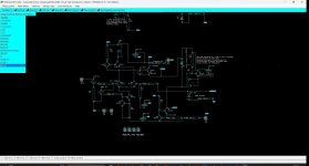
Did you built it? What about the sound ? Thermal stability ?Here is one I designed a few years ago.
View attachment 1182042
Happy with the responses ! Just by curiosity and my knowledge, I am interesting in this technology. I think I have very good starting point !
you had this little thing that worked well, it's a Velleman K8060 kit still available from gotronic and others at prices varying from 1 to 10 but overall it can be bought at around 25€ per channel.
I've often used it years ago to put music in empty or non-repairable boxes.
https://www.velleman.eu/downloads/0/illustrated/illustrated_assembly_manual_k8060.pdf
https://www.gotronic.fr/art-ampli-mono-200-w-622.htm
I've often used it years ago to put music in empty or non-repairable boxes.
https://www.velleman.eu/downloads/0/illustrated/illustrated_assembly_manual_k8060.pdf
https://www.gotronic.fr/art-ampli-mono-200-w-622.htm
It is the "curtain" that is drawn into the sound. The individual sound of each component. Also describable as "colored and/or dirty glass wall".I dont see how an amp can be hazy and foggy, yet extremely High resolution. To me that would be low resolution.
Your experience has probably been with underbiased IGBTs/Mosfets.
And: There are significant sonic differences, characters between the different transistors MosFet and Bipolar. And also IGBT. And it does not matter in which place, in which function they are used.
I would advise against larger construction types. Again, the reason is the lower definition of the current, the signal.
Worked great, even sold a few on ebay.Happy with the responses ! Just by curiosity and my knowledge
Did you built it? What about the sound ? Thermal stability ?
Happy with the responses ! Just by curiosity and my knowledge, I am interesting in this technology. I think I have very good starting point !
Was thermally stable.
IGBTs were originally intended to be used as switching devices, not as devices that would be biased up into a linear operating region. You can do that, I 'spoze, but why bother? With the bipolar & MOSFET devices we have available, I see no point in using IGBTs in that application, since the BJT's and MOSFETs are more than up to the task.All the IGBT I tested: extremely high resolution, extremely fine, but very hazy, foggy, tired.
Where do you play high power amps ?
In any case, none are intended for audio use by the makers.
I do know of a maker who uses IGBT drives for voltage controllers, response time is 15 mS, and volts to within +/- 1 V at 220V
Those are Fairchild devices, you can search for them.
The company's controller range starts at single phase 1 kW, and goes up to about 250 kW, 3 phase.
1 kW / channel output at home?
Seriously?
What about the flat response and the rest?
We are in a DIY forum for power amplifier, IGBT are for power use : Why we can't use it for power amplifier ? It is for knowledge 🙂
I suppose you have different range of power IGBT ?
MOSFET are also very difficult to make linear power amp with, not very linear this device, it is a switch ! and hard to drive with the Cgs capacity.
IGBT seems a little easier to use.
I suppose you have different range of power IGBT ?
MOSFET are also very difficult to make linear power amp with, not very linear this device, it is a switch ! and hard to drive with the Cgs capacity.
IGBT seems a little easier to use.
Last edited:
Have a look at this:
https://www.diyaudio.com/community/threads/giesberts-igbt-amplifier-elektor-1995.156966/
I have built it in 1995 and is still playing well.
https://www.diyaudio.com/community/threads/giesberts-igbt-amplifier-elektor-1995.156966/
I have built it in 1995 and is still playing well.
- Home
- Amplifiers
- Solid State
- Looking for IGBT amplifier schematics?