Some of my best results so far have been with EPS skinned with Kraft paper. Kraft paper is quite heavy though (95gsm) and has nice damping properties depending on the adhesive. It seems this very thin paper might be very interesting. Lighter, and maybe different damping properties.
The only reason I don't use paper skins is because the finish is fragile and subject to damage from gefingerpoken from das rubbernekkin. I'd have to put a grille over it for protection purposes.
The only reason I don't use paper skins is because the finish is fragile and subject to damage from gefingerpoken from das rubbernekkin. I'd have to put a grille over it for protection purposes.
Do you mean "DAEX25FHE4 Framed High Efficiency 25mm Exciter"???Hello xsuper,
A DAEX25FSE-4 is not too bad with poplar plywood or in the canvas DML I have.
A free exciter won't produce sound. Some membrane is needed.
From the theory I know (by the way, need some evidences), HF comes with rigid and heavy material (let say rigid and heavy enough).
Have you tested plexiglas or acrylic? Not tested from my side but they are said not too bad in HF, for the efficiency it is not the same!
What is very bad in frequency figure? What is your target?
Christian
https://www.daytonaudio.com/product/1177/daex25fhe-4-framed-high-efficiency-25mm-exciter
https://www.daytonaudio.com/images/resources/295-224--dayton-audio-daex25fhe-4-specifications.pdf
Yes this one. sorry for the typo.Do you mean "DAEX25FHE4 Framed High Efficiency 25mm Exciter"???

I get nice highs with these exciters on EPS and Polyfoam. Hybrid's as well, wood/EPS.Do you mean "DAEX25FHE4 Framed High Efficiency 25mm Exciter"???
JohnnoG
https://www.vegware.com/uk-en/page/our-materials/#materials-plants
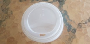
I came across this tea cup lid Made by vegware.
Although it says it has a shelf life of about one year.
Steve.
https://www.vegware.com/uk-en/page/our-materials/#materials-plants
I came across this tea cup lid Made by vegware.
Although it says it has a shelf life of about one year.
Steve.
Attachments
Just putting this idea out there for comment:
I think this is what's happening with the whole bandwidth vs efficiency problem.
The simulation below represents different system Q's (Quality factor) for the same cut-off frequencies. I think the Q is analogous primarily to the density and weight of the panel. The highest efficiency and narrowest bandwidth seems to correspond to very lightweight panels—EPS, XPS etc— and the seemingly widest bandwidth corresponds to heavier panels such as plywood, glass and acrylic.
The top end of the response can be extended by using harder panel materials, and the lower end can be extended by larger panel size and the correct edge damping. But of course the harder materials are generally heavier too, and so the general principle seems to stay the same.

Unfortunately I've blown up the mixer that I was using to phantom power my measuring mic, and I cannot prove the above. So I've resorted to modelling the curves while I look for a replacement interface.
I think this is what's happening with the whole bandwidth vs efficiency problem.
The simulation below represents different system Q's (Quality factor) for the same cut-off frequencies. I think the Q is analogous primarily to the density and weight of the panel. The highest efficiency and narrowest bandwidth seems to correspond to very lightweight panels—EPS, XPS etc— and the seemingly widest bandwidth corresponds to heavier panels such as plywood, glass and acrylic.
The top end of the response can be extended by using harder panel materials, and the lower end can be extended by larger panel size and the correct edge damping. But of course the harder materials are generally heavier too, and so the general principle seems to stay the same.
Unfortunately I've blown up the mixer that I was using to phantom power my measuring mic, and I cannot prove the above. So I've resorted to modelling the curves while I look for a replacement interface.
This somewhat matches my experience.. Using thin but relatively heavy 5 ply Blackwood resulted in a reasonably flat and extended response over that of Poplar, particularly at the LF end, but at the expense of lowered output levels, to the point where I put it aside.and the seemingly widest bandwidth corresponds to heavier panels such as plywood, glass and acrylic.
Eucy
Hi AndréJust putting this idea out there for comment:
I think this is what's happening with the whole bandwidth vs efficiency problem.
The simulation below represents different system Q's (Quality factor) for the same cut-off frequencies. I think the Q is analogous primarily to the density and weight of the panel. The highest efficiency and narrowest bandwidth seems to correspond to very lightweight panels—EPS, XPS etc— and the seemingly widest bandwidth corresponds to heavier panels such as plywood, glass and acrylic.
The top end of the response can be extended by using harder panel materials, and the lower end can be extended by larger panel size and the correct edge damping. But of course the harder materials are generally heavier too, and so the general principle seems to stay the same.
Unfortunately I've blown up the mixer that I was using to phantom power my measuring mic, and I cannot prove the above. So I've resorted to modelling the curves while I look for a replacement interface.
In DML, The efficiency and the HF extension (low pass) seem linked as you mention.
The LF extension is driven by the geometry (larger panel, lower resonance). In a certain way, even if there are some limits, the area is a variable that comes in addition to the material.
At this step, I won't choose a band pass (my understanding of what you describe) as model but more as a product of a low pass (efficiency and HF extension) and a high pass (area driven).
Christian
I'm finding it difficult to find information on the weights of the Plastic replacement materials, but do recall there being mentioned weights being similar to a commonly used plastic. So I am assuming quite low Grams per m2.
Just joined and very interested in this topic but have a lot catching up to do. So rather than show my ignorance and not sure if it has been posted. But there may be some interest in thin layers of this material.
https://www.scientificamerican.com/...-speeding-bullet-mdash-it-rsquo-s-super-wood/
https://www.scientificamerican.com/...-speeding-bullet-mdash-it-rsquo-s-super-wood/
Agreed. The model I presented is simply a combined HPF/LPF, with the passband Q's adjusted from around 0.7 to 1.2 (just to make the curves look nice.)Hi André
In DML, The efficiency and the HF extension (low pass) seem linked as you mention.
The LF extension is driven by the geometry (larger panel, lower resonance). In a certain way, even if there are some limits, the area is a variable that comes in addition to the material.
At this step, I won't choose a band pass (my understanding of what you describe) as model but more as a product of a low pass (efficiency and HF extension) and a high pass (area driven).
Christian
The background to the example comes from designing double manifold sub-woofers. I noticed that the efficiency/bandwidth product in double manifold subs seemed to reflect exactly the same problem as with DML panels.
Hi AndreJust putting this idea out there for comment:
I think this is what's happening with the whole bandwidth vs efficiency problem.
The simulation below represents different system Q's (Quality factor) for the same cut-off frequencies. I think the Q is analogous primarily to the density and weight of the panel. The highest efficiency and narrowest bandwidth seems to correspond to very lightweight panels—EPS, XPS etc— and the seemingly widest bandwidth corresponds to heavier panels such as plywood, glass and acrylic.
The top end of the response can be extended by using harder panel materials, and the lower end can be extended by larger panel size and the correct edge damping. But of course the harder materials are generally heavier too, and so the general principle seems to stay the same.
View attachment 1180788
Unfortunately I've blown up the mixer that I was using to phantom power my measuring mic, and I cannot prove the above. So I've resorted to modelling the curves while I look for a replacement interface.
Can you show the frequency for reference?
The composite board shared by @jamienelson before should be the right way
I have tested different densities of EPS stacked together
The frequency band of the loud volume has been widened
The above is for your reference~
But the material I have is too small
So there is no way to continue testing
@homeswinghome @toddincabo
Then I am more curious about the shape of "ears" and "irregular"
Does the shape make the frequency response flatter?
Have you done any testing on this?
Thanks everyone for sharing~
Then I am more curious about the shape of "ears" and "irregular"
Does the shape make the frequency response flatter?
I used the spring-steel spider Tectonic TEAX32C30 drivers for both of the panels below. They are expensive drivers, and seem to have a better HF than all of the Daytons I've tried so far (0.1mH inductance!) but I was not impressed with their buzzing and rattling that I had to deal with.
I've tried several different shapes. This star shape was okayish. I had been working on baffle diffraction simulations for the tweeters on an open baffle system for a customer, and this shape was very good for a baffle. So I thought I'd see what the results would be as a DML panel of the same dimensions. This was a foam-core paper panel.
Ovals are also quite good, but driver positioning is more critical than for rectangular panels.
This one was a single sheet of polycarb TwinWall, 900mm x 400mm, glued to a single sheet of 10mm EPS of same shape and size. Of course 2nd-harmonic distortion was too high because it's all unbalanced due to the elasticity/compressions of the front and back faces being asymmetrical.
These are both rabbit trails worth further investigaton. The oval needs to be put into a symmetrical construction and re-tested and optimised if the FR is good enough.
Looking at these old files, maybe I should test Tectonic drivers again. Maybe I got duds the first time.
I learned a new knowledge "inductance" and "high frequency" today...👍I used the spring-steel spider Tectonic TEAX32C30 drivers for both of the panels below. They are expensive drivers, and seem to have a better HF than all of the Daytons I've tried so far (0.1mH inductance!) but I was not impressed with their buzzing and rattling that I had to deal with.
I just happened to be testing "Edge", "Basta" today...🤣I've tried several different shapes. This star shape was okayish. I had been working on baffle diffraction simulations for the tweeters on an open baffle system for a customer, and this shape was very good for a baffle. So I thought I'd see what the results would be as a DML panel of the same dimensions. This was a foam-core paper panel.
But I want to put an OB tweeter on it first
Wait until the DML high-frequency test is completed before replacing it.
Not happy listening to music every day without good high frequencies
How to judge "Second Harmonic Distortion"?Of course 2nd-harmonic distortion was too high because it's all unbalanced due to the elasticity/compressions of the front and back faces being asymmetrical.
Waiting for your good news~Looking at these old files, maybe I should test Tectonic drivers again. Maybe I got duds the first time.
Thank you so much for sharing~
Those who think their ears are the best judge of speaker performance might comment on the "warmth" of the sound when they hear even-harmonic distortion.How to judge "Second Harmonic Distortion"?
Guitar over-drive circuits are made to produce 2nd and even harmonic distortion... And maybe Beethoven's fifth might sound better like that, maybe not. I suppose it depends what one likes.
Measurements will expose different kinds of distortion better than the ear will.
Hi AndréSome of my best results so far have been with EPS skinned with Kraft paper. Kraft paper is quite heavy though (95gsm) and has nice damping properties depending on the adhesive. It seems this very thin paper might be very interesting. Lighter, and maybe different damping properties.
The only reason I don't use paper skins is because the finish is fragile and subject to damage from gefingerpoken from das rubbernekkin. I'd have to put a grille over it for protection purposes.
Would you share more data about this EPS skinned : EPS density, thickness, glue, glue quantity, final weight, frequency response in HF ?...
Thank you
Hello Xsuper,@homeswinghome @toddincabo
Then I am more curious about the shape of "ears" and "irregular"
Does the shape make the frequency response flatter?
Have you done any testing on this?
Few tests for now on my side with this "ear" shape but no evidence of a big advantage. To be continued.
I forgot to comment on your ear shaped design when you posted it a while back.
Bertagni came up with that shape and if not mistaken was licensed to Yamaha. In both Bertagni and Yamahas design the ear shaped is used as a mid/woofer. That shape is not intended to be used for higher frequencies.
Bertagni came up with that shape and if not mistaken was licensed to Yamaha. In both Bertagni and Yamahas design the ear shaped is used as a mid/woofer. That shape is not intended to be used for higher frequencies.
Poor old trees!!!...We can't grow enough of them now, let alone if we make more stuff from wood!Just joined and very interested in this topic but have a lot catching up to do. So rather than show my ignorance and not sure if it has been posted. But there may be some interest in thin layers of this material.
https://www.scientificamerican.com/...-speeding-bullet-mdash-it-rsquo-s-super-wood/
And what an indictment on the human race that the making of bullet proof vests is a testing priority..
Note that it doesn't stop bullets quite as well as Kevlar, but it only costs a fraction as much... So who gets the Kevlar vests??
Ah me oh my
Hey teacher, leave them trees alone. 🤣🤣🤣 We dont need no wooden vest. We dont need no expensive Kevlar. All you need is fiberglass material and fiberglass resin. All in all its just another break in the wall made of trees. In my Pink Floyd voice. 🤣🤣🤣
- Home
- Loudspeakers
- Full Range
- A Study of DMLs as a Full Range Speaker