
Because I want to explain why I don't like making too many amplifiers.So why are you posting on a DIY site, if you 'don't love it'?
Tell someone who likes DIY like this.
I don't think DIY is a pleasure. Or hobbies.
DIY is just for a cheaper price. Get high-quality. High performance. And personalized products.
Not for DIY. Go DIY.
If a product. It doesn't make me feel satisfied. You give it to me as a gift. I won't accept it either.
Because it would waste my space.
If there comes a day when…. Top notch amplifier. Their selling price is the same as my DIY price. I will definitely make a direct purchase
I don't like DIY.
But high-performance amplifiers are too expensive. So I can only DIY.
So I won't waste time. Spend time on low-performance amplifiers.
No it isn't. It is a class A amplifier driving a class C amplifier.QUAD707 is a class B amplifier.
I don't know why you single out the 707. It isn't materially different from the 606 or 909.
yes. It is a class A driven class B amplifier.No it isn't. It is a class A amplifier driving a class C amplifier.
I don't know why you single out the 707. It isn't materially different from the 606 or 909.
There is a difference between 707 and 606. But the difference is not very significant.
Mainly because it has made some minor modifications. Let high-frequency. Better low-frequency performance.
Very simple modification. Just a few resistors and capacitors are different.
So I think 707 is better than 606. After all, they are almost the same situation.
Why don't I make a better 707. And to do 606 with some drawbacks.
Under the same architecture, 707 should be the best.
As for 909. I'm not sure yet. If you have any information, you can let me study it.
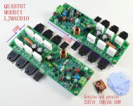
Attachments
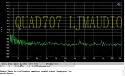
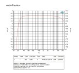
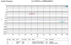
I compared and measured QUAD405 with QUAD707No it isn't. It is a class A amplifier driving a class C amplifier.
I don't know why you single out the 707. It isn't materially different from the 606 or 909.
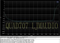
Their performance varies greatly.
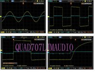
QUAD 405 SR 4V/US. QUAD707 SR 25V/US
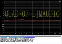
QUAD 707 Better bass. Better midrange. Better treble.
Attachments

No, it is a class A driven class C amplifier. The power transistor stage is unbiased. Ergo the conduction angle < 180 degrees, ergo class C.yes. It is a class A driven class B amplifier.
I use a Hypex NC122MP based amp during the summer months. Compared with my DIY valve amps, an ACA and a Quad 303 power amp (both driven by a Whammy) the Hypex is very 'clean' and powerful sounding but not as much fun to listen to.
I hear some of the class-d amps can sound a little cold and sterile, guess that's the class-d signature. Transistors amps sound a little kind of warmer - a generalization i know, hope i don't get shot down in flames. I mean is the warmth a sign of distortion, that the sound is being altered
So you wouldn't say that the nc122mp offers much of an improvement over the quad?
Not heard a Quad 405 so can't say, sorry. The Hypex amp offers performance in a small and efficient package, but getting a module for a DIY amp can be difficult and relatively expensive.
PS: Also changed R30/31 560R 2W for 3W and 1cm above the surface of the board as they get hotIf looking for a reasonable low cost replacement there are the LJM QUAD405-2 with the 2SC5200 and TL071. Make sure your search includes the "-2" and the "2SC5200". That is the version I would buy if I was to buy new boards again. I would also replace the op-amp (later, after successfully installing and testing the stock board) with OPA134. I also have a habit now of replacing the power transistors on all such boards with genuine Toshiba 2SC5200 purchased from Mouser or Digikey (ONLY a real authorized distributor).
Hi, i just acquired 2 boards you mention, i tested first for some days, then i changed C1 as for factory it came with 1uF and did the mod opa134 and 1.5V input sensivity. 100nf across c5 and across C2. and 100uF 63V across C15/16, and thats it, works very good connected to a Quad44 at the 1.5V output Before i changed C1 the sound was not pleasant, the output transistors look legit, or at least they work fine.
https://pt.aliexpress.com/item/4000648238280.html?spm=a2g0o.productlist.main.59.48f51cd5vXANM6&algo_pvid=82b72127-5813-4e6f-ac1c-689dc87ab6de&algo_exp_id=82b72127-5813-4e6f-ac1c-689dc87ab6de-29&pdp_npi=3@dis!EUR!53.09!37.7!!!!!@21227f0f16829253642732041d0745!10000010481964640!sea!PT!0&curPageLogUid=GAhztcSzgLRa
Last edited:
That isn't a kit as far as I can tell. That looks like a real QUAD405-2. (Based upon the surface mount current limiter module and the green transistors. (And the appearance of a number of other parts and the PCB.)
So are you looking to replace these boards, repair them, restore them, refurbish them or?
If looking for a reasonable low cost replacement there are the LJM QUAD405-2 with the 2SC5200 and TL071. Make sure your search includes the "-2" and the "2SC5200". That is the version I would buy if I was to buy new boards again. I would also replace the op-amp (later, after successfully installing and testing the stock board) with OPA134. I also have a habit now of replacing the power transistors on all such boards with genuine Toshiba 2SC5200 purchased from Mouser or Digikey (ONLY a real authorized distributor).
If you want to restore those boards there are others who might be better sources of information. (I have clones, I have never bought an original QUAD405.)
Two possibly useful links:
https://liquidaudio.com.au/quad-405-2-power-amplifier-restoration/
https://keith-snook.info/QUAD-405-2-Modification.html
The transistors are fake, have seen a few youtube videos
Agreed. It also has more electrolytic capacitors a than a real 405-2. It seems to be some clone , ancient enough to have attracted the attention of Quad's patent lawyers.
I´ve done most of the mods but failed to achieve the d13 one, i dont know what i made wrong but when i switch on the transformer makes a hum, puting back to original the hum is gone, i dont know if i need to change anything else before as it has the protection circuits from 12565 issue 3
The 2 watt 0.5 ohm resistors at the top of the board, do i have to use current sensing resistors to replace these.
They are current sensing resistors, by function. That's not a resistor type. Why do you think you need to replace them?
Thanks. Saw current sensing resistors for sale on the cpc website, so thought there may be something different about them than the usual through hole.
Are the current sensing resistors worth upping from 2watts to 5 watts power handling
Are the current sensing resistors worth upping from 2watts to 5 watts power handling
Not sure if they are underrated, but there are more 2 watt resistors next to the current sensing resistors, which are 560ohms and everyone else is changing these for 5 watts and raising them up from the circuit board.
Also do you think it may be worth using a c-r-c filter with the quad. I am thinking of soldering caps on the underside of the boards, underneath the 0.1uf caps next to the fuses.
Nelson pass uses crc filters in his amplifiers and from what I can gather, caps do not really reduce noise, they just shift the noise to a different / higher frequency that you cannot hear. Only the resistor in the crc filter can actually reduce noise. I have the 10,000uf caps in the power supply, then a 0.5 ohm resistor, then I can solder 2200uf caps on the underside of the amp boards. Do you think this may lead to a smoother DC and an improvement in audio quality
- Home
- Amplifiers
- Solid State
- QUAD 405 clone