@AllenB we all know YOU can do. Maybe others are not so "pro"?
By the way, rewinding coils is quite usual. If I build 3 identical speakers (for HT), I often find the coils to have quite wide tollererances. I like them all the same, so I match caps and rewind/ adjust coils. Is it neccessary? Maybe not, but the final measuring usually gives remarkable identical response, as todays good quality chasssis are remarkable constant too.
It may be cheaper to get an inductance meter from Ama/Bay and rewind old coils you have in the box than buying just a single pair of new ones.
One of the main limitations isn't so much how, but knowing what to fix.
On the surface it may be handy to be able to quickly try all possible filter combinations. Typical acoustic problems can't be fixed through a crossover. A person won't be any closer to knowing the solution in such a case.
On the surface it may be handy to be able to quickly try all possible filter combinations. Typical acoustic problems can't be fixed through a crossover. A person won't be any closer to knowing the solution in such a case.
Last edited:

I would try some minimalist approach like 12 dB filters for every driver only taking care for the correct crossover frequencies not taking much care of the frequency response. And apply some overall kind of in room fir correction at listening position.
This would correct also for all the phasing faults of such a multi way speaker.
Luckily for my one way fullrange driver projects I can measure in the near field of 20cm to get everything right.
For a big project with paper cone which goes loud I would choose a Fane Sovereign 15-300tc
https://www.diyaudio.com/community/...w-distortion-with-a-2-way.334757/post-6711040
Please don't judge me a heretic posting this.
I know that in a listening test a classical four way would have no chance in competing with this 38cm fullrange driver. With both boxes eq 'Ed with iir dsp to flat response. Because of phasing issues in the 4 way.
Just give this driver a try but you would have to buy it used.
Attachments
Last edited:
In a car with big volume goes insanely loud with 100db watts per meter efficiency
https://www.diyaudio.com/community/threads/new-15-full-range-fane.308652/post-6921091
https://www.diyaudio.com/community/threads/new-15-full-range-fane.308652/post-6921091
I would try some minimalist approach like 12 dB filters for every driver only taking care for the correct crossover frequencies not taking much care of the frequency response. And apply some overall kind of in room fir correction at listening position.
I have finetune it now!
All drivers have 12dB filter except the JBL 2405h how has an18 dB filter ( a little diffucult driver hahaha)
Coaxial "fullrange" had so far not been my"cup of tea"...But i never say never.
Ehhh, try all possible filter combinations ??....In a 4 way its probably a billion combinations, so of course i havent done that.One of the main limitations isn't so much how, but knowing what to fix.
On the surface it may be handy to be able to quickly try all possible filter combinations. Typical acoustic problems can't be fixed through a crossover. A person won't be any closer to knowing the solution in such a case.
And typical acoustic problems i dosen´t have at my home, most likely because of 6 meters in high and leaning from 3,4 m.
I also have planks with 55 mm intervals throughout the ceiling, and many angels in the house.
Regards John
So now have i spend a few days on finetuning the speakers, i managed to improve the JBL E145 curve and also a little "over all"
The 16 ohm JBL 2405h give me the most "problem"...My plan was to use it from around 7K, but it was "impossible" to integrate real good at that point with the Aga driver.
So eventually i ended up at around 9,5 K 18 dB filter, and have notice the Aga driver will run "all way" if i want.
And 20 ohm Aga driver work from ca 750 to 9,5K with a 12 dB filter
The 8 ohm JBL E-145 ended up at about 150 to 750-800 hz 12 dB filter
And the 8 ohm JBL 2235h from bottom up to 150 hz, with 12 dB filter.
The curve from before and new "new" finetunded curve.
Measured from 2,6 meter, mic at 84 cm high on axis
Best regards John
Attachments


I am not suggesting it 🙂Ehhh, try all possible filter combinations ??
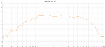
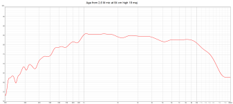
The old Aga driver from around 1975 impress me mutch, it can be used from 5-600 hz and up if you want!.
This is from 2,6 meters mic at 84 cm...with 2 of my 12 dB filter.
Edit, dont know witch "curve/filter" i use, so put both pics in!
Reagrds John
This is from 2,6 meters mic at 84 cm...with 2 of my 12 dB filter.
Edit, dont know witch "curve/filter" i use, so put both pics in!
Reagrds John
Attachments
Last edited:
I am not suggesting it
Hahaha, I would need 3 lives for that 😉
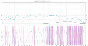
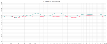
Now i have finetuned the overlap/crossingpoint between Jbl E145 and Aga driver at 7-800 hz.
Blue yesterdays filter and Red todays finetuned filter.
Allen you who are very knowledgeable,.have you any advice to give me about chooseing crossingpoints ?
For ex in my case between the 15 inch jbl e145 and the old Aga cd.
Regards John
Attachments
We do not have polar responses for the buttcheeks horn. I am not sure of anything, and not sure there is a best place to cross them to this 15". I am guessing the place you have chosen (7-800Hz) is OK, because the horn will go wide by then and might meet the 15". It may also be closer to axisymmetrical by then.
However, this doesn't give you the chance to offload the horn before it goes wide. That would require a choice of horn and woofer that come together at an angle, say 90 degrees. This would mean a higher cross for the 15", like 900-1200... It may even mean a larger horn or a smaller woofer.
However, this doesn't give you the chance to offload the horn before it goes wide. That would require a choice of horn and woofer that come together at an angle, say 90 degrees. This would mean a higher cross for the 15", like 900-1200... It may even mean a larger horn or a smaller woofer.
We do not have polar responses for the buttcheeks horn. I am not sure of anything, and not sure there is a best place to cross them to this 15". I am guessing the place you have chosen (7-800Hz) is OK, because the horn will go wide by then and might meet the 15". It may also be closer to axisymmetrical by then.
However, this doesn't give you the chance to offload the horn before it goes wide. That would require a choice of horn and woofer that come together at an angle, say 90 degrees. This would mean a higher cross for the 15", like 900-1200... It may even mean a larger horn or a smaller woofer.
Thanks for the information Allen 👍
Maby i try out to cross the E-145 a little higher.....like 950 hz or around.
Does this PDF on the horn help you?
Regards John
Attachments
David Smith used 1khz as a crossover point.
https://www.audioheritage.org/html/profiles/jbl/4430-35.htm
https://audio-database.com/JBL/speaker/4430-e.html
https://www.audioheritage.org/html/profiles/jbl/4430-35.htm
https://audio-database.com/JBL/speaker/4430-e.html
Yes, looking at the PDF this looks better than I was thinking. There should be a good place to cross in the region we're talking about.
And the horn have a unusually good side and rear spread.
Maby because my horn "goes all around" on the sides.
Regards John
If you have overlapping ranges, XOs could be optimised in order to:
- minimise THD (measure!)
- using less step filters (less, better components)
- matching directivity (measure) - smooth / equal directivity through the speaker is a good thing.
Are you in belive that more expensive komponents are much better TNT ?
Personally, I'm doubtful, even if I don't use "the cheapest" caps and coils, resistors.
Use to have a little "better" caps on tweeters and midrange, but most often not alll of them ( instead i mix if the value is uneven)
On woofers i always use cheep caps.
How do you mean when you say "minimise THD ?
Change the xover again or use another crossingpoint ?
I perceive the speaker as having very even sound dispersion in the room, & even if I stand or sit or walk around a bit, I perceive the "sound image" similarly
Regards John
David Smith used 1khz as a crossover point
Thank you puppet, real interesting reading 👍
Regards John
Not really - the only thing I would not do is using coils with iron.Are you in belive that more expensive komponents are much better TNT ?
Personally, I'm doubtful, even if I don't use "the cheapest" caps and coils, resistors.
Use to have a little "better" caps on tweeters and midrange, but most often not alll of them ( instead i mix if the value is uneven)
On woofers i always use cheep caps.
How do you mean when you say "minimise THD ?
Change the xover again or use another crossingpoint ?
I perceive the speaker as having very even sound dispersion in the room, & even if I stand or sit or walk around a bit, I perceive the "sound image" similarly
Regards John
Measure the drivers distortion and see which one is better in the overlapping region - if everything else is equal...
Abrupt change in how wide/narrow the speaker disperse at XO (or elsewhere) is a thing that reveals a speaker... not wanted.
//
Not really - the only thing I would not do is using coils with iron.
Can you explain why ?
My "hero" Albert Von Schweikert was probably the world's best xover designer, and he did crossover systems for Polk, Klipsch, JBL, ESS Heil, Infinity, Apogee, Cerwin Vega, Jensen, NHT and many others.
He developed the first three-way Heil Air Motion Transformer speaker with linear phase crossovers.
Product of the Year Award,” for his Lucas Film THX design, and was contracted by companies such as Lucas Film THX, Walt Disney, Steinway, A&M Records, Sheffield Sound Labs, Mobile Fidelity, and JVC and others.
Do you mean he was wrong?
He always use coils with iron up to 200 hz, and the photo shows when i fix a broken xover 15 years ago.
The speaker was the awardwinning Von Schweikert VR-4 upgraded to VR5-7
Regards John
Attachments
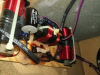
He was not wrong - I assume he was under some sort of budget so he made a vise compromise with the inductors. The problem is the worst kind of distortion - hysteresis. Usually "we" dont need to do that compromise if we can stay out of very low frequency XOs.
//
//
- Home
- Loudspeakers
- Multi-Way
- How to measure a 4 way with "big" distance between drivers?