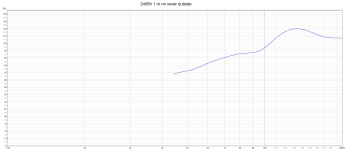
So driver is 48cm above the ground and microphone is 1.21m above the ground.measuring distance is 1 meter, height of driver cc 48 cm and microphone is 121 cm up
344/(SQR(12+(0.48+1.21)2)-SQR(12+(1.21-0.48)2))
= 474Hz
0.5 wave dip at 237Hz
1.5 wave dip at 711Hz
2.5 wave dip at 1185Hz

I'd say still... also measure each driver from close distance and observe their individual contribution and post them here. Disconnect other drivers while doing one of them if possible.
//
//
I have never attempted to measure such a large design, or a 4 way so I am really out of my comfort zone.
There is lots of useful advice here.
I think TNT comments in post 22 above seem sensible then other people can see where you are going. i am sorry to suggest this but maybe on axis and + and- 30 degrees to get a better view of how things come together.
Maybe with this info imported into VituixCad you get get a feel for the combined responses and a power response which will be useful i think.
As its a sloping baffle, because I don't know you will either have to measure each driver at a distance of 1 metre and apply the offset for the slope at that position in VituixCad , or simply maintain that initial measurement distance and go up in height then they are all referenced at 1 m distance maintaining phase at that point which may be the easiest option, and probably aligns with what you are doing.
HiFi Jim has been round this loop if i remember correctly,, but I cannot identify the thread and post No.
I haven't read back in this thread but a useful reminder of the driver frequency bands may help guide useful comments, especially the midrange horn does it have specs.
I know they are heavy and not easily moveable and the weather isn't great just yet so take care and keep warm.
I am sure when you have finished it will give you that Big Jawen sound you are chasing. I was going to add vintage, but i am not sure if that is part of the sound t you were hoping to replicate ?
What is wrong with the sound? You've made an inside measurement pretty much at listening distance and listening height, right?

It doesn't look that bad, what made you ask the question? What part would you want to change? Quite heroic to drag this big boy outside for some measurements, but it does look like you did it for some random experiments at best. You need a better plan for an action like that. What are you trying to correct?
It doesn't look that bad, what made you ask the question? What part would you want to change? Quite heroic to drag this big boy outside for some measurements, but it does look like you did it for some random experiments at best. You need a better plan for an action like that. What are you trying to correct?
What is wrong with the sound? You've made an inside measurement pretty much at listening distance and listening height, right?
This is my big DIY speaker project which I worked with for a relatively long time.
The cabinet was DIY made before this project but for a 3 way, so I have rebuilt the box & modified it to be a 4 way.
I am after the "old" big JBL sound, so that is my goal. ( love these papercones)
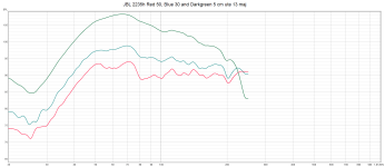
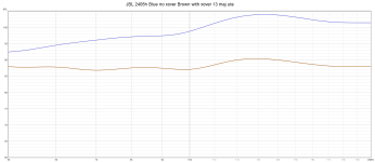
Using a 8 ohm15 inch JBL 2235h woofer in about 126 liter mounted at the side working up around 150 hz.
Tuned to ca 28 hz with 2 ports with total area of 160m3 ( one in top of speaker and one at the bottom pointing forward)
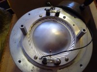
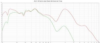
A 8 ohm JBL E-145 15 inch in ca 30 liter working from 150 to ca 7-800 hz.
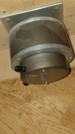
An 20 ohm old Swedish cd from AGA made around 1975 ( with some license from Altec Lansing, and i think its like the 299 series)
Weight 10 kilo and 34 kilo with the JBL clone of 2344a (baby check) massive horn.
Use it from ca 800 hz up to 7000 hz.
! I have no data specs from this driver !
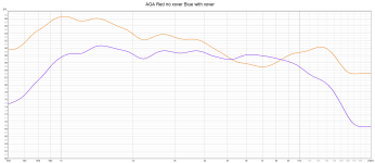
And a 16 ohm JBL 2405h at the topp from 7000 hz.
Im not an expert so my project is "trial and error" with many hours.
And making a xover for 2 pieces of 16 ohm driver and 2 pieces of 8 ohm drivers, has been difficult.
Used VituaxCAD to SPL Trace my inside mesaurement, and have done impedance Trace from the 2405h specs, E-145 specs.
But diden´t find 2235h impedance and have no impedancecurve from the AGA driver either.
Then ive spend many hours building xover, but much "trail and error" in VituaxCAD because program and reality are miles from eachother.
The sound now with my diy xover is real sweet, so only final tweaking left to do.
Is VituaxCAD usable even with 2 pieces of 16 ohm drivers, when VituaxCAD uses "default 8 ohm" on these ?
Best regards John
Attachments
I'd say still... also measure each driver from close distance and observe their individual contribution and post them here. Disconnect other drivers while doing one of them if possible.
Here is all invidual measurements from 1 meter both without and with my diy xover.
Best regards John
Attachments
Measuring outside will potentially allow you to see certain things in the measurements, but note that unless you are measuring in a semi-anechoic environment (like a highly elevated above ground or perhaps ground plane measurements on flat, featureless terrain), you will be measuring early reflections, too. Typically the excess group delay and spectrogram plots are not paid proper attention to (time or arrivals, etc.), so features in the measurements are mistakenly interpreted.
The real issue with taking measurements outside and perhaps farther away than 2 m is that the measurements no longer inform about the loudspeakers in-room where boundary gain and unavoidable early reflections (like those off the loudspeaker enclosure itself) interact with the direct arrivals from the loudspeaker's drivers, and interference band interactions (i.e., lobing) turn into early reflections in typically sized listening rooms.
Chris
I have never attempted to measure such a large design, or a 4 way so I am really out of my comfort zone.
Hallo Ray 🙂
Hahaha almost all diy-speaker-work is out of my "comfort zone" 😉
But learning is "trail and error" and many hours....Keep the head intact.
Have done as TNT ask for and post all invidual mesaurements 👍
/John
Here's more info than you probably looking for, and it's directed at large scale live-sound.
But the same principles and science apply to smaller speakers too.
https://www.prosoundtraining.com/2010/06/28/far-field-criteria-for-loudspeaker-balloon-data/
But the same principles and science apply to smaller speakers too.
https://www.prosoundtraining.com/2010/06/28/far-field-criteria-for-loudspeaker-balloon-data/
Hi Jawen,
If you didn't have all the impedance traces it must have took many hours of trial and error. Brilliant effort on your part.
The overall trace you posted looks good, and as you say starting to sound sweet. So good luck with the final voicing.
if your compression driver and horn asssembly are known items can you get the original data, if not all of it the horn intended frequencies and verify you are in line with that data. Then maybe its the second driver Xover that needs shaping to make the transition smoother is it difficult to do something with the 500Hz bump and the roll of to the horn. Maybe see if there is a way of keeping its level extending downwards as it also comes back at 2Khz, but it doesn't make it through to your overall response? So probably a non issue.
You must have a large spares box of resistors, coils and capacitors to get yourself this far and i guess waiting for the components to arrive in the post.
I hope its been a sunny day, for you.
If you didn't have all the impedance traces it must have took many hours of trial and error. Brilliant effort on your part
Thanks for kind words Ray 🙂
Yeeeeeees.....many hours!
Everything i change in Vituaxcad "that looks good", had a completely different change in reality....
Even not near the frequency i was trying to change hahaha
My compression driver is from an old Swedich company called AGA/Baltic, and they where very likely the biggest electronics company in the world & produced almost everything.
And they sold out part of the company to Philips around 1977, and some parts become superbig swedish Ericsson 1983.
But they had 70% of all Swedish cinemas soundsystems the during the 60s & 70s, so they where big.
And the 70s was the absolut best regarding to production and quality.
But just found a museum and a few pictures and treads on old simular drivers, and of course ads from Asia.
https://www.filmsoundsweden.se/backspegel/aga_hogt.html
https://www.hostboard.com/forums/f700/280808-h805-adapter/index2.html
https://www.aga-museum.nl/aga-techniek/
regards John
Are all other drivers disconnected while measuring an individual?Here is all invidual measurements from 1 meter both without and with my diy xover.
Best regards John
//
Are all other drivers disconnected while measuring an individual?
On woofer and tweeter mesaurement ( up to 150 hz and over 7000 hz) i forgot to disconnect, because REW suddenly shut down by itself and I lost all previous readings, so I had to redo everything.
But on lowmid and midrange (from 150-7000 hz) all other drivers was disconnected.
And i find a mesaurement for the tweeter alone also, here it is.
So now all mesaurements except 2235h up to 150 hz is with all other drivers disconnected.
Regards John
Attachments
in such situations I prefer single nearfield measurements above approximately 250-300Hz incl. crossover network for each driver resp. chassis and compare/modeled the measured curvatures by adjusting crossover network nearly the theoretical resp. ideal characteristic (e. g. low pass and high pass with BU-III or LR-IV characteristic is a good choice so I still think).Just want to ask you experiance people.
Whats the "most" honest/correct metod/way to mesaure when you use a big 15 inch driver from 150-600 hz, and have 44 cm between lowmid and midrange (600-7000 hz) , and also 28 cm up to tweeter ( 7K and up) ?
So i have 72 cm from center 15 inch lowmid up to center "tweeter".
obviously I can't measure from 1 meter & have the microphone between center treble and center mid range ( as i use to)
Is 2 meter enough and should i put the microfone between the tweeter and lowmid?
Best regards John
as an example check out therefore the frequency responses of Linn's NEXUS in image 2 (post #37) under
https://www.diyaudio.com/community/threads/linn-nexus-ls250.254849/page-2
(own measurements).
check out also this thread:
https://www.diyaudio.com/community/...-like-avalon-eclipse-which-advantages.206768/
and the measurement method in Stereophile of Avalon's Eclipse
https://www.stereophile.com/content/avalon-eclipse-loudspeaker-measurements
In the case of four-way versions, the same rules apply as long as the crossover frequencies are far enough apart.
Below 250-300 Hz I don't like nearfield measurements - in such cases the position of microphone is still in the position of listening place (e. g. for level so as crossover frequency adjust in case of added subwoofer).
I have to admit I missed your measurement in post #5 - it looks rather good - what are you missing? Why the urge to measure?
Taking the general problem with mic measurement and hearing difference into account - I think you simply measure what the situation is at the mic - its really not more to it. Far away you get a summing around x-over regions and the contribution from the room.
Where you place the mic (and gating settings) really matters for what you want to use the measurements for - do you have an idea about this?
//
I understand your measurements now and it seems you build a very nice speaker. Even a 3-way is a close to impossible task for the majority of hobbyist's, so well done. I really admire your result and have quite an idea how much time and money you may have spent over the years.
In your case, to improve something, the logical approach would be to go active, first removing the huge coils and caps in the low range.
With your very well made passive set-up, to get anything better, if possible at all, will cost you a fortune in coils and caps with unpredictable results. More components do not result in better sound, that is another point.
So my first approach would be one or two 4x4 DSP's with matching amps. As you sure have some amps, using good PA stuff for the lower region will improve control and response without breaking the bank. If the active low end turns out nice (it is hardly impossible not to get an audible better result), you can go active for the upper range, too. A good compromise is to use a passive x-over between horn and tweeter, such a 3-way active still gives you DSP control over the high range while using your favorite amp, which will sound much better, free of the bass load.
Just one warning, once you went active, it is very hard to go back. If you got such a great result passive, what are you able to do with a DSP?
By staying with PA gear, you will set up the whole hardware in symetric connections. This is fast, reliable and well sounding simpler than the usual HIFI stuff. Don't start with soldering stuff as many do to save a few $$. This only distracts from the cause. The best thing, if for some reason you don't like the PA components, selling them with very little loss is always an option, while HIFI gear is loosing a lot of value the day after you bought it.
Maybe have a look here: https://www.thomann.de/se/index.htm...LCJjdXJyZW5jeSI6OSwibGFuZ3VhZ2UiOjV9&reload=1
Last edited:
what are you missing? Why the urge to measure?
Hard to know what im missing before i hear it 😉
No i was in on tweaking the last finish on the filters.
And this is also my first horn-build with compression driver, and im afraid to damage my ears because they are so powerful and just throw the "sound" on you.
I often listening on music for 4-5 hours, so it can´t be even a little "to hot", it´s killing my ears and head if it is.
And a wise gentleman from England learn me that 1-2 K was a importent frequency, which should not have + 2-3dB
And probually other frequency regions also is "more" dominant in human hearing, so i must try to awoid these.
Often listening at 110+ dB
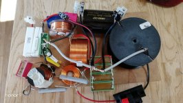
This is the filter without a 10mH coil and 330 uF for the JBL 2235h woofer.
Regards John
Attachments
I understand your measurements now and it seems you build a very nice speaker. Even a 3-way is a close to impossible task for the majority of hobbyist's, so well done. I really admire your result and have quite an idea how much time and money you may have spent over the years.
In your case, to improve something, the logical approach would be to go active, first removing the huge coils and caps in the low range.
With your very well made passive set-up, to get anything better, if possible at all, will cost you a fortune in coils and caps with unpredictable results. More components do not result in better sound, that is another point.
Thanks for your kind words Turbowatch2.
Don´t have so much money to spend, so most things i have from before and the coils for example i wind and re-wind, and also use small pieces of iron to change the values....and mostly cheap caps.
So time and to be " a little stubburn" is the key, and think this speaker in total have cost me around 1.200 Euro/1.400 $, if i count what i pay´d for the parts at the time i invested in them.
They play BIG and with extremely detailed midrange/AGA...don´t know if ivé ever had hear so realistic voices before from a speaker.
But also afriad to make the filter "to hot"...Kills you hearing quite fast even before you know it happends.
I have a active filter in my other stereosystem that i can try out, and also a Crown xti amp with inbuildt active xover and EQ.
Your words "A good compromise is to use a passive x-over between horn and tweeter" is exactly what i have in the other stereosetup, active xover for woofers and mid/twe splitt att 340 hz feeding 2 stereoamps, and a passive 2 way xover inbuildt in the MTM.
Regards John
Since passive components have become more expensive than high end drivers, for a typical 2-way for example, passive is audiophile luxury. DSP controlled active is the new low price-high quality approach. You hardly find any passive monitor speaker any more. Not because it is worse than passive, but cheaper and better, if you consider that any individual room is a part of the speaker.
If you, for example, go for a 120€ DSP and a 300€ 4-channel amp, all you need are a few cables and you have a professional active base.
If you own the a DSP Crown amp, you know what you can do with it...
If you, for example, go for a 120€ DSP and a 300€ 4-channel amp, all you need are a few cables and you have a professional active base.
If you own the a DSP Crown amp, you know what you can do with it...
Since this leans on uncertainty and doubt, I will say this. I am able to get same results with passive, active, or a combination. It is a matter for the skill of the crossover designer.If you got such a great result passive, what are you able to do with a DSP?
Good choices and use of resources.most things i have from before and the coils for example i wind and re-wind, and also use small pieces of iron to change the values....and mostly cheap caps.
- Home
- Loudspeakers
- Multi-Way
- How to measure a 4 way with "big" distance between drivers?