
After playing with values I was able to find ones that worked.
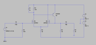
Output voltage swing is limited to +14.3V and -10.5V into 500R load.
Voffset at the output is 16mV.
Looks like it is comfortable driving loads all the way down to 150 ohm.
Output voltage swing is limited to +14.3V and -10.5V into 500R load.
Voffset at the output is 16mV.
Looks like it is comfortable driving loads all the way down to 150 ohm.
Attachments
Last edited:
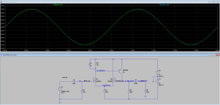
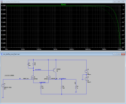
Frequency response is limited by C1 capacitor and can be 100nF for audio frequency applications.
If wider frequency response is needed, C1 can be reduced to 10nF.
If wider frequency response is needed, C1 can be reduced to 10nF.
Attachments

H
HAYK

looking at currents.
Changing R1 to 10K made the Fets around 1ma
so probably worked better.
likely should be around 2ma since no mirror.
then you can fine tune DC offset with R3
which will probably come down to 1 or 2K ish
Main concern is R2 at 200 ohms ?
think that BC656 is little hot at 75 ma ?
Dont know what you want the current to be.
seems high. In the model sure it drives
loads no problem.

Linear Systems or Linear Integrated Systems.
One of the better current manufactures for Fet
The have single package LSK170 N channel
and a dual matched N channel on same die LS844
One of the better current manufactures for Fet
The have single package LSK170 N channel
and a dual matched N channel on same die LS844
Increasing R2 limits negative voltage swing. What would you recommend for its value to be safe current for BC856?Main concern is R2 at 200 ohms ?
think that BC656 is little hot at 75 ma ?
Dont know what you want the current to be.
seems high. In the model sure it drives
loads no problem.
Can you elaborate more?I'm not sure a 2N7002 is a good choice here, it is a power FET after all.
JFET's.
Reason for choosing 2N2007 is because I kind of want to hear how it sounds. I want to make JFET version too and try give it a listen and compare both. Just for fun.
Last edited:
Nothing wrong with experimenting. It would be a bit like using TIP41's as the input pair of a differential input stage but it could equally sound really good.
The power FET will have a much higher gate/source junction capacitance for one thing and the noise will be high compared to a JFET. I'm pretty sure the small signal gain or transconductance will be low for the FET.
The power FET will have a much higher gate/source junction capacitance for one thing and the noise will be high compared to a JFET. I'm pretty sure the small signal gain or transconductance will be low for the FET.
H
HAYK
Wake up, 2n7002 is 60v 300ma transistor. In TO92 it is 2n7000.Nothing wrong with experimenting. It would be a bit like using TIP41's as the input pair of a differential input stage but it could equally sound really good.
The power FET will have a much higher gate/source junction capacitance for one thing and the noise will be high compared to a JFET. I'm pretty sure the small signal gain or transconductance will be low for the FET.
https://assets.nexperia.com/documents/data-sheet/2N7002.pdf
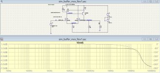
Bootstrap idea sounds nice, will try to sim it later some timeTry with bootstrap. The distortion is nearly halved and the fr is over 20Mhz.
Last edited:
The 2N7000/7002 has capacitances comparable to a J112 FET, and the dispersion in threshold voltage must be comparable, maybe even smaller for the MOS, thus little to be gained there.
Instead of a shunt compensation, a more classical dominant pole scheme could be used, with a small capacitor (22p to 47p) between the B and C of the BJT.
For a robust buffer, not too sensitive to loading effects by cables, etc. including an emitter follower in the output might be a good idea. Depends on the finality
Be something similar to what @Mooly did in post #7Increasing R2 limits negative voltage swing. What would you recommend for its value to be safe current for BC856?
He's keeping current down to 8 or 10ma
And added compensation R8 and C1 to make it feasible Stable at unity gain/or gain
this circuit really wont drive low impedance loads.
without making the current very high, which is melting transistors.
It is rather fun though, because I been thinking about doing a
N channel fet differential circuit for something.
So is inspiring for sure.
A discrete opamp with power section is more likely approach.
And would use something like Mooly's compensation
to make it unity stable
I was hoping to be able to drive 600 ohms at least. So there’s no way?this circuit really wont drive low impedance loads.
without making the current very high, which is melting transistors.
- Home
- Source & Line
- Analog Line Level
- Need help simulating discrete impedance matching buffer in LTSpice - using 2N7002 and BC856