Additionally I have found a few commercial designs that I haven’t seen on this thread that others may want to see to get ideas or inspiration.


Hi JamieOther ortho-planar springs, this one in heavy 1/8th inch maple, it’s a work in progress - given the crazy dip at 4khz.
View attachment 1171521
View attachment 1171522
View attachment 1171523
I just realized that having a comparison of the board prior to the cuts would be good…
I’ll get some of those shortly
I love this left field idea 👍
I presume the coil area is free of neoprene
3mm seems to me at least to be very thick for damping... Have you tried a thinner layer??
I'll have to try this..
Cheers
Eucy
Interesting. I came on a report on testing cone speakers intending to remove the effect of reflections. Place mic close to the speaker. Some small % of the diameter. A paper it was referring to reckoned it predicted far field to within 1db removing the need for an anechoic chamber.Graph below is with the Dayton calibration mic at 10cm.
It's mentioned in this video but but can't recollect any mention of maths. Lost the link and can't find it again
Mention of stepped sweeps is interesting,
Veleric ,Earborne,
I like it. That's basically the same framing method I used for this pair, only I routed the inside corner rather than add the quarter round. I think recessing the plate a bit like Deude suggested is a good idea to protect the plate (especially if its PS).
What foam are you planning to use?
Eric
View attachment 1167247View attachment 1167248
In your panels pictured , was that 3 mm Poplar Ply and what type of adhesive / foam did you use ?
I did some testing today with 3mm Poplar 970 x 600 panels , one mounted to its frame with VHB double sided tape and the other mounted with soft 6 mm window sealing foam.
I wasn't totally happy with either and will try removing the VHB and 6mm foam and fitting a harder rubber foam around 2 - 3 mm thickness.
I found the following ;
the soft 6 mm foam mounting lost around 25 % volume compared to the VHB tape
soft 6 mm foam was approximately 15 - 20 % dull on guitar and violin compared to VHB tape mount.
the VHB tape panel had more volume but it also had some nasty resonance (death rattle) around 200 - 800 Hz.
VHB tape panel was cleaner and sharper on female vocals , and violin music (1800 - 2500 Hz) was also clearer.
I suspect the 6mm soft foam is causing a dissipation of energy so i will rinse - repeat with a harder duro rubber around 2 - 3 mm and run the tests again.
Quoting my own post here..🤭Hi Jamie
I love this left field idea 👍
I presume the coil area is free of neoprene
3mm seems to me at least to be very thick for damping... Have you tried a thinner layer??
I'll have to try this..
Cheers
Eucy
I've been thinking about this some more and I'm intrigued by it... It will be good to see the comparison with the unsprung panel/s
The spring will reduce the panel stiffness and increase the pistonic motion in the exciter location, but the cuts must also have a considerable blocking/edge/reflection effect on transmission through the panel. For 3 ply material in particular, the stiffness of the spring legs will also vary considerably because of anisotropy, making detailing tricky
Could such a spring also conceivably reduce the apparent size of the panel by limiting transmission?
If a reduction in local stiffness is all such a spring does, how different is the effect from selective local thinning of the panel? Thinning will not result in planar displacement is one difference, are there others?
There's quite a lot going on here I think
Eucy
Last edited:
No interest in the video I posted - cost of that software arrives via a quote. Few links that may be of interest. 😉 They do interest me.
https://audiojudgement.com/measure-speaker-frequency-response/
For DML's pointing at the sky may be adaptable.
Less costly software
https://audiojudgement.com/quasi-anechoic-loudspeaker-measurements/
https://audiojudgement.com/loudspeaker-measurements-part-2/
There is also soundeasy but locked to user via a usb stick.
AjohnL,No interest in the video I posted
I liked it! Thanks for that and the other links. I have little doubt the splicing technique works for conventional pistonic speakers. But I'm not so sure if can work for a dml.
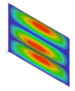
Due to the modal nature of DML panel, the result you measure in the nearfield depends entirely on how close the mic is to the nodes and antinodes of the plate's natural frequencies. Consider this mode below, and assume for the sake of discussion that the frequency corresponding to this mode is 100Hz. If you place the mic in front of the exact center of the panel, you will get a very strong response at 100 Hz. But if you place the mic a few inches up or down (directly in front of either of the blue nodal lines for that mode), the response you measure at 100 Hz will be much, much lower.

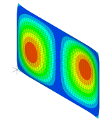
On the other hand, for this mode below, which happens at say 75 Hz, you get very weak response with the mic in the center of the panel, or offset either up or down along the vertical centerline. But if you move the mic a few inches left or right, (away from the blue nodal line for that mode), you will start to get a much stronger response at 75 Hz.

So, unfortunately, any nearfield mic location will "overwieght" some modes and "underweight" others, depending on how close or far the mic is from the nodes and antinodes of each of the modes.
This feature actually makes nearfield measurement a great tool for helping to analyze the modal shapes and frequencies of dml panels. But it makes it much more difficult I think to apply the splicing technique for simulating anechoic response.
Eric
Of course! What I meant by posting it was “look even with this heavy wood, the ortho planar spring is effective, apart from that dip at 4khz (which is a resonance I can deal with shortly) the spl of the high and low frequencies is quite level”Hi Jamie
I love this left field idea 👍
I presume the coil area is free of neoprene
3mm seems to me at least to be very thick for damping... Have you tried a thinner layer??
I'll have to try this..
Cheers
Eucy
Without it, I see a dip of about 10-15 decibels for higher frequencies.
Quoting my own post here..🤭
I've been thinking about this some more and I'm intrigued by it... It will be good to see the comparison with the unsprung panel/s
The spring will reduce the panel stiffness and increase the pistonic motion in the exciter location, but the cuts must also have a considerable blocking/edge/reflection effect on transmission through the panel. For 3 ply material in particular, the stiffness of the spring legs will also vary considerably because of anisotropy, making detailing tricky
Could such a spring also conceivably reduce the apparent size of the panel by limiting transmission?
If a reduction in local stiffness is all such a spring does, how different is the effect from selective local thinning of the panel? Thinning will not result in planar displacement is one difference, are there others?
There's quite a lot going on here I think
Eucy
So what I have found is that for light materials like 1.5mm basswood sheets, the spring shape that works for harder materials like the walnut won’t work. And visa versa. It needs to be cut so that it has enough stiffness to transfer the frequencies below somewhere in the range of 2khz - 5khz, but keep the frequencies above on the springs center area.
I happened to make the spring too mobile, I tested adding a layer of rubber over the spring wanting to reduce its movement.
This is how I ended up with the neoprene gasket over the springs arms.
The resonances are very high in the arms, but adding the rubber over them took a majority of that away.
Suddenly the monolithic wooden panel has a high frequency area of movement, and a dampening layer to reduce those high frequency resonances, and then the monolithic area around the spring for the low frequencies.
It’s been a very repeatable experiment
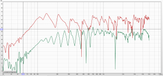
Here's an example of two nearfield measurements on the same panel:

The red trace is with the mic in the center of the panel, and the green trace the mic is several inches from one edge.
I admit it is a very extreme example. I don't think anybody would think to put the mic close to the edge like I did for the green trace. But it does demonstrates the issue I was trying to explain, which is that the nearfield response of a DML is extremely sensitive to the location of the mic.
Eric
I’m picking up a umik-1 today, and I am in the process of gluing together boards, mineral wool, and D40 foam triangles. Which is a lot more work than I anticipated. So that I can improve my grade of anechoic-ness.
Then I will feel confident to do measurements with the mic further away.
this is my existing echo reduction set up.

Then I will feel confident to do measurements with the mic further away.
this is my existing echo reduction set up.
For the low end I was thinking maybe point into the sky. I don't think the hole would be needed for dml. Sound deadening panels might even figure. Initially I am interested in rather small panels.
The gated measurement? Not sure. It depends on time to reflections. I've just read rather than thought about it. I need a bit more thought on that, The path distances for reflections appear to always be longer than direct. This is not an area I know anything about. 😉 Waves maybe but not sound waves in air.
I don't like spending money but may be tempted to buy ARTA. Pity REW doesn't include it as it's a rearrangement of the usual stuff.
LOL
It was 5.6 mm 5 ply poplar. I'd have been happy to use thinner if I could get it in 5 ply. This is not to say you can't use 3 ply, but it doesn't work well for my particular design, for reasons I explained in this post:Veleric ,
In your panels pictured , was that 3 mm Poplar Ply and what type of adhesive / foam did you use ?
https://www.diyaudio.com/community/...s-as-a-full-range-speaker.272576/post-7326424
For the surround I used 3M Extreme double sided mounting tape. I chose it because it had good damping properties, or at least I thought so at the time. But now I think I have a better handle on how to assess damping ability, and now I see it as decent at damping but far from the best.
So I'm heading in the opposite direction. I think energy dissipation at the perimeter is a good thing, and that the real challenge is to find materials that provide sufficient dissipation, rather than avoiding those that cause too much.I suspect the 6mm soft foam is causing a dissipation of energy so i will rinse - repeat with a harder duro rubber around 2 - 3 mm and run the tests again.
Eric
AjohnL,I don't like spending money but may be tempted to buy ARTA. Pity REW doesn't include it as it's a rearrangement of the usual stuff.
What exactly is it that REW doesn't include? Do you mean gated measurements? Is that the same as windowing, or something different? You can set a window with REW.
Eric

Yes with a stepped sweep. I started looking around after thinking about linear sweeps and thought if a pulse of a frequency was produce there would be a delay before the mic received reflections so a delay can allow a reflection free measurement to be made. Maybe i have missed something but that seems to be the general idea used. REW's - I've seen no examples of it being used this way. The other packages are pretty clear about this use. From memory going on the video reflections need to be >25db down, hence the advantage of use of near field for LF..Do you mean gated measurements?
😉 Mic still hasn't arrived so no measurements yet. Also a PC problem I wont go into. That is part resolved. I'll see how it goes,
I wonder if filling the spring slots with silicone or similar would be as effective as the neoprene?happened to make the spring too mobile, I tested adding a layer of rubber over the spring wanting to reduce its movement.
This is how I ended up with the neoprene gasket over the springs arms.
The resonances are very high in the arms, but adding the rubber over them took a majority of that away.
From the first page of the tutorial for ARTAAjohnL,
What exactly is it that REW doesn't include?
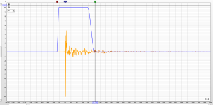
How this works ? We are sending an impulse through the speaker, and take a reading using the ARTA software. We can determine after how many milliseconds the first sound wave reached the microphone, and after how many milliseconds the 2nd wave have reached the microphone. The second wave is sound reflected from the nearest boundary (floor or ceiling etc), and it will be picked up by the microphone few milliseconds later.
Between these two, there is a time window (that’s why it is called gated), where the microphone picks up only the sound generated by the loudspeaker, therefore ignoring room reflections. This is all fine and dandy, but there is a catch. Depending on the size of the time window, the frequency response will be accurate until a certain point. The larger the distance, between the loudspeaker and the first boundary, the lower in frequency you can plot the response curve.
If REW does have it I hope some one tells me. The initial impulse test allows the time to the 1st reflection to be measured. The frequency content of the impulse is determined by it's rise time. The Dirac pulse is a mathematical type where the rise time is zero so contains all frequencies, infinity stuff. Conversely there is a simple constant that off hand I can't remember that relates bandwidth of an amp to it's rise time. Also square wave testing when the wave is viewed. It can be over damped, under damped or critically damped.
Near field testing is just using distance to increase the difference between the sound power of the measurement compared with the reflection. The mic is placed as close to the speaker as it can be. It can't be placed so close on DML's but ..... pass I have no idea if there is any gain to be had.
LOL Practicalities - arrange to measure the response accurately accounting for reflections and what happens in typical actual use - there will be reflections.
Your post is a couple of months old but i noticed Trojan Fibreglass supplies have 3mm and 10 mm XPS in a 80 kg3m density if its still of interest.From a performance viewpoint, I believe you'd be better off trying surfacing tissue/veil mat or ultra thin fibreglass cloth (0.03mm thick) with either polyester or epoxy resin coating to an XPS or EPS core of 3 to 5mm thick.
I'm considering making a flat bed type of hot wire cutter to try different thicknesses of XPS. I routed the last one... What a mess it makes.
Eucy
https://trojanfibreglass.com.au/product/maxxcore-pvc-foam-core/
They also have honeycomb panel but its also 80 kg3M , I cant see that being useful in the form its in , Some of the US guys have access to a 3 mm honeycomb which could have appealing attributes but i didnt find it available in Australia yet.
https://trojanfibreglass.com.au/product/pp-honeycomb-panel/
Thanks Earbourne... That product is PVC foam rather than styrene...I have no idea how that would sound.. Interesting though...
Cheers
Eucy
Cheers
Eucy
Hello Eucy,What mass values did you add, (or did I miss that detail??)
I used what I had... coins of 0.5, 1 and 2€ which are 7.5g to 8.5g... nothing highly scientific.
Next planned step is to test solutions do give an escape way to the air trapped between the membrane and the magnet. Air that flows through the voice coil and then the back. I would like to see the impact on this 2.5k hump and on the HF extension. For now, I don't see the dome as a solution to the 2.5k hump. For the HF extension, I don't see other solution with PP than a tweeter. To followSo far, I have completely failed to get anyone to try the coke dome....It's now your turn to be encouraged, even harassed to try it 🤞🙏... Particularly with the PP material, as it does have a 'soft' sound.
It will make a difference to the brightness, and it may also mitigate your 2.5k hump
Good to know. The connection of the external face of the corrugated PP to internal face which is driven by the exciter seems "weak". So why not. Next time in a DIY store, I will have a look to PU foam.Another idea I had for PP and have commenced a trial of (suspended until I return home) is this:
At the location of the exciter, I drilled small holes in the rear face into each flute, moving the location of each hole so they don't line up. I then injected PU foam into each hole, and was surprised at how easily and far it spread along the internal flutes (see attached photos) It made a mess on the injection face, but it trimmed off easily when cured.
Christian
- Home
- Loudspeakers
- Full Range
- A Study of DMLs as a Full Range Speaker