Mouser one click purchase was updated with parts available in stoc.
There are many parts modification, but a well designed project must work with a large variety of parts.
There are many parts modification, but a well designed project must work with a large variety of parts.


I only make plack pcb's, it isn't that hard to troubleshoot if you look at it at close distance with traces thick as these (even 0.254 isn't hard to troubleshoot). So no worries there 🙂 What i hate about black pcb's is that with cheap pcb makers like jlcpcb and pcbway, the quality (color density, layer thickness and uniformity) is not that consistent. Sometimes a batch is amazing, sometimes not so much. While green is always on point.
The ripple current is only one relevant value. Since the electrolytic capacitors are oversized with regard to the task of 50 Hz smoothing, other factors are important for the playing style of the amplifier. First of all, the Equivalent Series Resistance (ESR), which represents the internal resistance of the power supply in our application, should be mentioned. Next are influences which are not shown and which can only be found out by measurements and that is the behavior of the capacitor relative to frequency. This determines the characteristic map that describes whether the capacitor can supply current evenly, or whether it has a tendency to resonance at any frequencies and how its inductance behaves. All of these factors, which are not specified for cup electrolytic capacitors, play a role in evaluating the sound when used in an amplifier.Hello Tibi,
Since I will have a black pcb design, EPCOS also in black fits me better.
View attachment 1170397 View attachment 1170398
Would FQPF7P20 rand TK2K2A60F,S4X replace and FQP3P20 and FQP3N30 @ Q5 and Q6?Mouser one click purchase was updated with parts available in stoc.
There are many parts modification, but a well designed project must work with a large variety of parts.
Dear Tibi,
which components (transistors, resistors, diodes, etc.) do you recommend to match within one board and between stereo boards? To what parameter and with what tolerance? This would affect how many pieces one shall (or need not) buy in excess.
Thank you in advance,
Miklos
which components (transistors, resistors, diodes, etc.) do you recommend to match within one board and between stereo boards? To what parameter and with what tolerance? This would affect how many pieces one shall (or need not) buy in excess.
Thank you in advance,
Miklos
Thank you. I suppose the Q9/Q11 matching is about the Vgs threshold voltage. But is this really all about pairing components for this amp? No special attention needed to Q5/Q6 or to the output transistor pairs? Please do not assume that things which are trivial to you would also be trivial to me... ;-)
§of cYes, on Q9&Q11 Vgs must be matched.
Q5&Q6 are part of classA stage and do not need to be paired, matched etc.
Output mosfets must be close in Vgsth and transconductance, but this is not critical.
Q5&Q6 are part of classA stage and do not need to be paired, matched etc.
Output mosfets must be close in Vgsth and transconductance, but this is not critical.
Thank you, from this I conclude that one does not really need to stock up a large excess of the components for pulling the best out of your original version. Have a nice day, Miklos
The “magic” of this amplifier is that will sound good with a wide range of parts. Even IRFP240/9240 in output will deliver their best. IRF610/9610 in place of Q5&Q6 will deliver good sound as well.
What I strongly recommend is synchronous rectification in power supply and decent capacitors like epcos, vishay, nichicon, mundorf, bhc etc. You may voice the amplifier by changing them.
There is nothing to adjust and amplifier will start to shine after 300h.
What I strongly recommend is synchronous rectification in power supply and decent capacitors like epcos, vishay, nichicon, mundorf, bhc etc. You may voice the amplifier by changing them.
There is nothing to adjust and amplifier will start to shine after 300h.
Tibi,
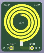
An amplifier with 2 pairs of transistors is capable of delivering a minimum of 300w into 4ohm (approx. 9A). How much current can the surface coil carry if I have pcb 2oz + immersion GOLD 1oz?
Thx.
An amplifier with 2 pairs of transistors is capable of delivering a minimum of 300w into 4ohm (approx. 9A). How much current can the surface coil carry if I have pcb 2oz + immersion GOLD 1oz?
Thx.
Considering that the coil must cover 20Hz-20KHz, a flat coil will perform considerably better than a 1mm wirewounded coil. Due skin effect, geometry and area are most important. The shape of flat coil will have larger surface area and proper geometry for high frequency operation.
If you want to calculate precisely, there are various tools on the net for such.
Hope this answer your question.
If you want to calculate precisely, there are various tools on the net for such.
Hope this answer your question.
Tibi, if I may, I would be glad to receive your opinion on the single pair / two pairs dilemma. I use large floor-standing speakers (Opera Divina Callas) with 8Ohm and 89dB. Their labels say 15-240W rms, which probably means to say that they shall be easy to drive. Indeed, I used to drive them with a 50W Class A power amp for a decade and they have never misbehaved. I wonder if a second pair of output transistors would possibly give or rather take in this setup. I will make my Mouser purchase following your latest BOM soon.
I will definitely use synchronous rectification (Saligny Standard bridges have arrived in perfect shape - thank you), quality components and most probably play around with capacitor brands, for curiosity.
The only PCB modifications I consider (with the least possible changes to the topology ) are putting the PSU and the 2 speaker relay mosfets (but not their control circuit) on board (I find less internal cabling appealing) and shrink everything into 80mm chassis height.
If you do this, than please use latest 2.9 ver fm github.It is also possible in theory to print the 1.2uH flat coil from Tibi's file on a separate small PCB for use elsewhere.
Stef.
- Home
- Amplifiers
- Solid State
- Q17 - an audiophile approach to perfect sound