Hi,
The LT3032 is subjectivly less good than the former, sound wise. ADP7102 ?
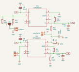
I would try to make at the voltage pins of the 861, two 0805 decoupling for acrylic caps, for instance the ones made by Panasonic. Not necessarily needed, but it is to balance the sound of the reg output cap. 0.1 uF.
The second 861 (buffer) must be configured in reversed mode according Audial's shematic.
If you can, you should try to put traces with two vias outputs to both try the circuitry with the buffer and without by outputting directly after the first stage.
the 150R output smd traces are fine, subjectivly though you can try an ALLENB 1/8W of the same value... very nice
The LT3032 is subjectivly less good than the former, sound wise. ADP7102 ?
I would try to make at the voltage pins of the 861, two 0805 decoupling for acrylic caps, for instance the ones made by Panasonic. Not necessarily needed, but it is to balance the sound of the reg output cap. 0.1 uF.
The second 861 (buffer) must be configured in reversed mode according Audial's shematic.
If you can, you should try to put traces with two vias outputs to both try the circuitry with the buffer and without by outputting directly after the first stage.
the 150R output smd traces are fine, subjectivly though you can try an ALLENB 1/8W of the same value... very nice
Last edited:
Nice I/V board, might be worth making a spot for a TH resistor so you can play around with diff types
Thanks for the feedback! I've attached an updated schematic with the ideas.
I can't seem to find a good negative voltage companion for the ADP7102. Do you have any recommendations? I could do something like this:

Seems unusual and not really recommended, but then I could use 2 ADP7102's?
I can't seem to find a good negative voltage companion for the ADP7102. Do you have any recommendations? I could do something like this:
Seems unusual and not really recommended, but then I could use 2 ADP7102's?
Attachments
@cibo ,the negative is ADP7182 but in 5-lead TSOT, so you can also order ADP7102 in the same case.
You can also use better regulators such as LT3042/3094.
I would leave the regulators outside the PCB with the OPA861 so you can try some other regs. The problem with the OPA861 or AD811 that I use is the small PSRR compared to a classic op amp, so the quality of the regulator and rectifier is extremely important.
I use a Walt Jung shunt reg with ADA4625 op amps for my I/V with AD811.
Attachments


It is indeed simplier for the power supply front end to use a dedicated negativ reg.
@grunf, I believe @cibo Is wanting to make a tiny integrated pcb as @Vunce gave to us from Pedja Rogic original idea but due to the parts shortage. So it has just to use dil8 op861 and diferent reg than the excelent TS7A family, sound wise. Something simple and tiny I mean.
@grunf, I believe @cibo Is wanting to make a tiny integrated pcb as @Vunce gave to us from Pedja Rogic original idea but due to the parts shortage. So it has just to use dil8 op861 and diferent reg than the excelent TS7A family, sound wise. Something simple and tiny I mean.
Last edited:
I was also convinced that passive I/V is the holy grail, but when you look at what you get with passive conversion, in my opinion active I/V is still better. For about ten years I messed around with passive and then you see that you lose dynamics, speed, details in the sound, not to mention the S/N ratio, which is especially important for PCM1794 if the I/V stage is not performed correctly.Is it a theoretical consideration, or have you had the opportunity to hear a well-made DDDAC with 4 boards and Sowter output transformers, and compared it with a PCM1794 DAC made according to the datasheet? What does real I/V stage mean? DDDAC has a passive I/V (I/U) stage, considered by many to be superior to any active I/V (I/U).
(however, the guys from Sowter don't think like me, but they recommend for the 1495 that the next stage has an impedance higher than 100k🙄)
Last edited:
Everyone has to decide for himself what he likes subjectively.
There is no absolute truth, only THD numbers.
But if that would be the only measure, then the world would be left with composite chipamps alone by now.
😀
Patrick
There is no absolute truth, only THD numbers.
But if that would be the only measure, then the world would be left with composite chipamps alone by now.
😀
Patrick
I agree, normally numbers and measurements don't say everything about the sound. But there are differences, whether it's a tube or SS amp, as well as passive and active I/V conversion, each has its own sound signature.
Now it's up to everyone what their ears (brain) likes, but I wouldn't take passive I/V conversion as a reference.
Now it's up to everyone what their ears (brain) likes, but I wouldn't take passive I/V conversion as a reference.
In the thread about DDDAC, many options of I/V are discussed on hundreds of pages. I know Doede is still sticking to passive I/V with a custom Sowter transformer. The output impedance of the DAC is low, so the load on the secondary can be quite small.I was also convinced that passive I/V is the holy grail, but when you look at what you get with passive conversion, in my opinion active I/V is still better. For about ten years I messed around with passive and then you see that you lose dynamics, speed, details in the sound, not to mention the S/N ratio, which is especially important for PCM1794 if the I/V stage is not performed correctly.
(however, the guys from Sowter don't think like me, but they recommend for the 1495 that the next stage has an impedance higher than 100k🙄)
Dear all,
Question: I am using AD1862 with I2SOVERUSB. On noise floor one can see the LRCK residuals. Tiny but exists (my whole board has about 1.4uV noise from 1 to 20khz). Can see it with no input signal of course.
I can understand why it may happen but is there a way to reduce it? While no signal in the DAC should switch 0 according to LRCK. It happens with my other DIYINHK board, based on stop clock.
Thanks,
Guy
I know the PCM1794 very well, its disadvantages and advantages because I started designing a DAC with it and I expected it to replace the existing one with the PCM1702. Then I wanted an 'active' I/V conversion with tubes which I discovered then and was delighted and already then problem appeared with the high output currents of only two PCM1794 in parallel and the impossibility of finding the ideal tube for that current.In the thread about DDDAC, many options of I/V are discussed on hundreds of pages. I know Doede is still sticking to passive I/V with a custom Sowter transformer. The output impedance of the DAC is low, so the load on the secondary can be quite small.
Now I would go the other way, two PCM1794, four AD811 , then something esoteric for the output buffer, although it could also be AD811 or even AD815 and all regulators would necessarily be shunt type right next to the PCM1794 on the PCB.
I wouldn't comment much about dddac here, but I still think that it can be done much better with PCM1794 and I consider that a challenge for my next diy DAC🙂
Attachments

Dear all,
Question: I am using AD1862 with I2SOVERUSB. On noise floor one can see the LRCK residuals. Tiny but exists (my whole board has about 1.4uV noise from 1 to 20khz). Can see it with no input signal of course.
I can understand why it may happen but is there a way to reduce it? While no signal in the DAC should switch 0 according to LRCK. It happens with my other DIYINHK board, based on stop clock.
Thanks,
Guy
Are you using some PCB designed by me? I did not hear any residual LRCK signal, it is dead silent while no music is present. Some players are stoping the LRCK signal immediately (VLC, youtube) and some are not (bsplayer).
Thanks Miro,
No I am using a PCB designed by my friend and me (I sent once pictures).
Anyway, you know it is straight forward. I am using Lyuben's board configured to AD1862 (style). Then a discrete hybrid I/V.
As a player I am using Audirvana (Mac).
Anyway, even if I am not connecting the USB cable, the LRCK residuals are on the latest or what ever the I2SOVERUSB is stacked on when turning on.
I will try to send a picture. It is possible to see it even with scope on 1mV/div and clearly with cosmos E1DA ADC.
It seems the I2SOVERUSB does not stop when no music is played. It also happens with the stop clock circuit in my other DIYINHK DAC (also AD1862).
Here is a screenshot of LRCK while no music and I2SOVERUSB stacked on 384k. I put cursors that you will be able to see, about 384k.

It is a common practice in USB-I2S boards to have WS (LRCK) and SCK (BICK) signals running all the time. Only SD (data) is stopped when no music is played.It seems the I2SOVERUSB does not stop when no music is played.
Have you checked if you have overshoot on LRCK or BICK?
2mV/div, simple TEK TDS1001B.
I have your board, MIRO, but not reachable now. I am using the I2SOVERUSB. I wanted to put a better registers on your board to see if I can reach 384K.
Could you try repeat my test (when you have time)
with your board? Put 384k or 192k and then put the scope on the appropriate settings, then freeze the shot and measure.
Thanks
I will check but if yes, what to to? Small series resistors on lines to AD1862?
It is a common practice in USB-I2S boards to have WS (LRCK) and SCK (BICK) signals running all the time. Only SD (data) is stopped when no music is played.
Have you checked if you have overshoot on LRCK or BICK?
- Home
- Source & Line
- Digital Line Level
- DAC AD1862: Almost THT, I2S input, NOS, R-2R