I think Marcel's circuit above is the simplest possible one that doesn't use a PLL. However, since you say "Lock indicator", I guess you're looking for a PLL-based solution. If so, refer to 74HC4046 , 7046 , 9046 datasheets, preferably the older ones from Philips.Hello!
I Need It for my Dac project.
So ...Is there a Simply electric diagram that use i2s signals to obtain with led indicator for
44,1khz
96 kHz
192 kHz
+ Lock indicator?
Thanks
Antonio
the simplest is the silego based freq detector, it is a about 2% accurate, and has minimal parts.
For TDA1541 based DAC i need to detect the lock on i2s signal'Lock' for what, a dac? For a SPDIF receiver?
Okay. How are you defining 'Lock' in that case? Usually 'Lock' is for when a PLL has locked onto an incoming clock frequency. IIUC, TDA1541 does not have an internal ASRC or PLL, so 'Lock' refers to some other thing here?
Hi! can you share link or info please?the simplest is the silego based freq detector, it is a about 2% accurate, and has minimal parts.
In the past I have used the DATA signal as a lock source + a transistor and some resistors and of course an LEDOkay. How are you defining 'Lock' in that case? Usually 'Lock' is for when a PLL has locked onto an incoming clock frequency. IIUC, TDA1541 does not have an internal ASRC or PLL, so 'Lock' refers to some other thing here?
Markw4
Enough for me a Simply wiring diagram that uses i2s signals to be obtained with signaling LEDs for 44.1kHz 96kHz 192kHz.
Enough for me a Simply wiring diagram that uses i2s signals to be obtained with signaling LEDs for 44.1kHz 96kHz 192kHz.
Maybe something like post #6, but with the spare Schmitt trigger and the lower monostable multivibrator connected to the data signal, with the monostable multivibrator's RC time increased to a millisecond or so.
The same disclaimers as for post #6 apply. 74HC123's from Nexperia or TI, definitely not Toshiba.
Last edited:
Thanks.....Maybe something like post #6, but with the spare Schmitt trigger and the lower monostable multivibrator connected to the data signal, with the monostable multivibrator's RC time increased to a millisecond or so.
1) Data out= lock funtion?
2) Is possibile calibrate resistors/caps for?
44,1
92
192
Regarding 2), please change the 15 kohm resistor of the second monostable multivibrator into 8.2 kohm in series with a 10 kohm trimming potmeter, and the 6.8 kohm resistor of the third monostable multivibrator into 3.9 kohm in series with a 5 kohm trimming potmeter. Trimming potmeter with wiper and one fixed contact to the +5 V, resistor between the other fixed contact and the capacitor.
In the present you will (just like in the past) use a receiver IC that often has a pin for the lock LED. Which receiver IC do you use?In the past I have used the DATA signal as a lock source + a transistor and some resistors and of course an LED
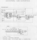
Jean Paul...i know...but i spoke of i2s input...i Need to read fs on a dac connected to CD transport or USB card via RJ45 connectors.
Instead yesOK which USB card?
You are not using RJ45 for I2S are you?
Attachments
- Home
- Source & Line
- Digital Line Level
- Simple LED display for DAC freq?
