The regulated supply used in my vers of Crowhurst's Twin Coupled Amp solves all of those problems. Except one, covered at the end.Regulating the driver supply may be successful; regulating the anode supply for a 300B is much more difficult. Using series-regulator in a power stage can easily degrade the sound, unless you are very well equipped to optimise it. Using kludgy architectures like the Maida is very likely to sound bad.
The voltage handling required of the semiconductors must account for transients, including a startup and shutdown - and a 500V FET in a 435V output will be far too close. the power handling & heatsinking must accommodate the ±10% likely range of the Line/mains voltage, and handle overcurrent events.
There is a current limit on the primary supply. Two IRF FETs are arranged so that at turn on they share the HV transient. After a short delay Q2 assumes most of the voltage drop. It is on a Wakefield Heatsink. R116 & C103 form a delay on the run up of the HV until negative grid bias reaches the power tube grids.
Not required for Cathode Bias.
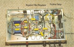
All these modules are built on the bench before installation. There was a lot of preliminary work on the physical layout. And the circuit. Full Differential, 6SL7, 6SN7 but can be switched to Crowhursts front end by one toggle switch. The amp is PP 6LU8s driven by the triodes in the 6LU8s. Maxs out at about 35W & easily scalable. There are no boutique parts. And built at a fraction of the cost of other dreams we see these daze.
It is an experimental amplifier. So how the B+ regulation effects the sound I have no idea. My objective is that the Rolling Stones & Pink Floyd sound the way they recorded, complete without the mystical 2nd harmonic crap.
Attachments
-
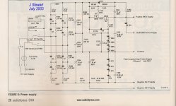 Figure 6 Power Supply Clone of Twin Coupled Amplifier w Caption.jpg213.4 KB · Views: 406
 -
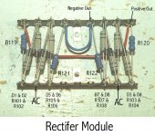 Rectifier Module.jpg112 KB · Views: 350
 -
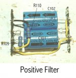 Positive Filter.jpg56.1 KB · Views: 272
 -
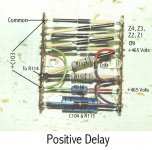 Positive Delay.jpg111.6 KB · Views: 258
 -
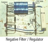 Negative Filter & Regulator.jpg105.5 KB · Views: 254
 -
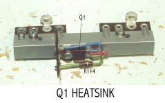 Q1 Heatsink.jpg80.9 KB · Views: 258
 -
 Underside of Chassis.jpg478.4 KB · Views: 365
I would like to build this skunkie amp amp and I have a couple of questions:
- since I will be using DC for the 300B what is the point of the trimpot across the filament? I have seen schematics with the cathode bias attached directly to the neg. supply side of the filament. Is balancing the filament load still critical?
-I will have 5VAC secondaries for the 300b heater so I won't be able to use regulators as they need higher drop. I was planning a rectifier and CRC filter with r=0.1 or something like that. Will that work?
-unfortunately my transformer will have a 0-6.3-10VAC secondary for the 6SN7 heaters. Can I hook the 10V tap to the voltage divider to raise the filaments of the 6SN7 by the prescribed 50V? I may have to tweak the divider a little bit. Or is it better to create a virtual ct between the 6.3 V taps?
Thanks,
Check out the section on “bias hum” here: https://ttradio.net/we-300b-single-ended-end-amp-discussion-we300b-245/
Also Paul Joppa’s post of October 25, 2009 here: https://www.audioasylum.com/cgi/vt.mpl?f=set&m=62954
Also Paul Joppa’s post of October 25, 2009 here: https://www.audioasylum.com/cgi/vt.mpl?f=set&m=62954
Last edited:

@Francois G
The links were interesting, I learned an interesting tidbit about OT primary impedance vs. the value of the last cap in the power supply.
However, I m not closer to an answer for my questions. According to the TentLab site, using his board it seems OK to omit the hum bucking pot.
The links were interesting, I learned an interesting tidbit about OT primary impedance vs. the value of the last cap in the power supply.
However, I m not closer to an answer for my questions. According to the TentLab site, using his board it seems OK to omit the hum bucking pot.
You can try the build without humpots. I will cost nothing and may work. Or you may end up with objectionable hum. I’m no expert in this matter, so I hope they, the real experts, will chip in. What follows is my understanding of why you will want to install humpots. This explanation is based on one given by member @6A3sUMMER in https://www.diyaudio.com/community/...into-a-6b4g-set-worth-it.396990/#post-7297184
The goal is to set at each end of the filament at about 5V/2 = +/- 2.5V relative to the bias voltage when you use a 300B with 5 volt filament. That makes one end of the filament 2.5v higher than the self bias voltage; and the other end of the filament be 2.5V lower than the self bias voltage.
The negative end of the DC powered filament draws more current than the positive end of the DC powered filament, and the purpose of the humpot is to divide the voltage so as to place the logical middle (or virtual center, not the physical center) of the filament (only accessible inside the tube) at exactly the self bias voltage with +2.5 V to one side and -2.5 V to the other.
Let’s take for example in the ”Get Set Go” design (www.diytube.com) discussed in the thread linked above, where the humpot was replaced by a combination of a 47 Ohm and 52 Ohm resistors after it was empirically determined that these resistances generate the +/- 3.15 V on each side of the filaments’ “logical center”, best cancelling hum for the 6B4 power tubes in that design. If you swap the 47 and 51 Ohm resistors, versus the + and - 6.3VDC supply, you will get unbalanced voltages versus the self bias voltage which is hum-inducing.
Since tubes can differ I believe it is best to have the humpot installed to accommodate such variances.
I’m not sure what you are asking here. A hand drawn schematic may help.unfortunately my transformer will have a 0-6.3-10VAC secondary for the 6SN7 heaters. Can I hook the 10V tap to the voltage divider to raise the filaments of the 6SN7 by the prescribed 50V? I may have to tweak the divider a little bit. Or is it better to create a virtual ct between the 6.3 V taps?
Hard to predict without more details, what low-drop rectifier etc. Perhaps you could try to model it in PSUD2 https://www.duncanamps.com/psud2/ I know you have 5Vac windings (one for each 300B, right?), but Rod Coleman’s regulators come highly regarded, if you want to take the next step up.will have 5VAC secondaries for the 300b heater so I won't be able to use regulators as they need higher drop. I was planning a rectifier and CRC filter with r=0.1 or something like that. Will that work?
Francois,
if you check Skunkie schematic you'll notice the 0-6.3V for the 6sn7 heaters is center tapped. The ct is then lifted up by 50V to keep the heater potential below the 110V differential limit (as I gathered from watching the skunkie vid). In my case my secondaries will be 0-6.3-10VAC the question is can I connect the 10V tap to lift the filament voltage since I lack the center tap? The other way is to create a virtual CT between the 0-6.3VAC taps with resistors.
I hope I made myself clear.
Yes, I have two 5VAC (3 actually one for the rectifier) I will try the PSUD2 site and check the Colemans regs. Thanks for the links.
OK, I understand the 0-6.3-10VAC the question now, thanks. With the indirectly heated 6SN7 you have flexibility - I would tape off the 10 V tap and connect the lift voltage to either 0 or 6.3 Vac taps; no virtual CT needed in my opinion. I believe Stephe tied to the CT because she had it, and is elegant and symmetrical, but you should have no problems here. I believe the 5Vdc supply for the 300Bs will be more challenging to get quiet.
FrancoisG
"Hum-pots" are only for AC Powered filaments (and for DC filament power if it has lots of ripple, so get the ripple out).
Properly regulated DC filament supplies do not require "hum-pots".
If you have DC power to the filaments, and are trying to make the voltage on both filament ends equal to ground,
Then the resistors have to be un-equal.
So, some will use a pot (ok to find the proper values; but replace that with fixed resistors).
Never use a pot with a possible wiper problem, when you can use a pair of fixed resistors.
Just my opinions.
Thanks guys. That's 2/3 questions cleared.
I think that yes, the 5VAC is now my problem. I need higher voltage to get clean 5VDC.
I don't think I want to use LT1085. Based on what I read that's not the optimal option.
I think that yes, the 5VAC is now my problem. I need higher voltage to get clean 5VDC.
I don't think I want to use LT1085. Based on what I read that's not the optimal option.
Hi Grataku
I don't want to dissuade you but skunkie's amp is really not that great a design... Yes, you can cascode 6SN7 but it won't have much drive or swing for the 300b. Certainly not his cascoded 6SN7 which only draws only 4mA.
300b is not a cheap tube. It's hard to drive well. Cheap 300b amps sound boring, while cheap 2a3 amps can sound pretty GOOD.
The driver stage for 300b has to:
1. Swings lots of volts.
2. Low output impedance.
3. Has lots of drive. Not 4mA. Think 15-20mA (or more).
Its WAY better to sacrifice some gain to get BETTER drive for 300b. But then you could simply use 2a3 instead. 🙂
Now I see you are struggling with 5V heaters. Do yourself a favor and do 2.5V DC for 2a3 instead of 300b. The Cascoded 6SN7 will be ok for 2a3.
Plus if you are using 3.5K OPT's it will be a perfect match for 2a3.
Ian
This is really not a good idea. The whole heater will be swinging at an average of 10V - 6.3/2V = about 7VAC referred to the cathode. Just make a resistive divider and be done with it. Not a hill worth dying on.In my case my secondaries will be 0-6.3-10VAC the question is can I connect the 10V tap to lift the filament voltage since I lack the center tap? The other way is to create a virtual CT between the 0-6.3VAC taps with resistors.
All good fortune,
Chris
What's the right way to drive a 300B? I have read lots of strong opinions but comparatively few schematics or real options. I guess people that think have the best schematics jealously guard it. 😉300b is not a cheap tube. It's hard to drive well. Cheap 300b amps sound boring, while cheap 2a3 amps can sound pretty GOOD.
The driver stage for 300b has to:
1. Swings lots of volts.
2. Low output impedance.
3. Has lots of drive. Not 4mA. Think 15-20mA (or more).
I measured on a scope 140Vpp out of that cascode into the grid of the 300B. Have you actually tested this like I have to state that as being factual?Hi Grataku
I don't want to dissuade you but skunkie's amp is really not that great a design... Yes, you can cascode 6SN7 but it won't have much drive or swing for the 300b. Certainly not his cascoded 6SN7 which only draws only 4mA.
I honestly don't care if people build this or not, I know mine sounds great and it blows away that "JC Morrison/sun audio" design that shows up everywhere.
I get emails from other folks who have actually built it and they seem to enjoy it too. Is it "The best"? Never claimed it was, but it is a fairly simple design that works.
BTW this is how the final version of this amp tested, seems to have enough drive for a 300B tube to me:
P.S this type of rude misgendering etc is why I rarely post on this platform anymore. It does get old and is unnecessary.
Last edited:
They like to make building a 300B amp "out of reach of mere mortals" and insist you need $5000 worth of magic transformers etc or don't bother even trying...What's the right way to drive a 300B? I have read lots of strong opinions but comparatively few schematics or real options. I guess people that think have the best schematics jealously guard it. 😉
Centre the steering wheel and put the hammer down 🙂What's the right way to drive a 300B?
Sorry, could not resist...
AFAIK cascodes have high-ish output impedance. It maybe that indeed this is not the most ideal way to drive a 300B on paper. Who knows? At the same time, a 300b amp with crappy damping factor may not be the ideal way to drive a speaker to begin with. That is, if you listen to solid state amp enthusiast. 😉 I learned to focus on testing, and I listen and research when helpful suggestions are given. I would say so far the interactions have been rather positive. 😎I measured on a scope 140Vpp out of that cascode into the grid of the 300B. Have you actually tested this like I have to state that as being factual?
I understand. Some of my (much) older designs hidden on this board lead to people writing me messages here too. Then I explain what I am doing now and they are disappointed that there isn't a free lunch.I measured on a scope 140Vpp out of that cascode into the grid of the 300B. Have you actually tested this like I have to state that as being factual?
I honestly don't care if people build this or not, I know mine sounds great and it blows away that "JC Morrison/sun audio" design that shows up everywhere.
I get emails from other folks who have actually built it and they seem to enjoy it too. Is it "The best"? Never claimed it was, but it is a fairly simple design that works.
BTW this is how the final version of this amp tested, seems to have enough drive for a 300B tube to me:
P.S this type of rude misgendering etc is why I rarely post on this platform anymore. It does get old and is unnecessary.
I don't do youtube - it's full of clickbait and I always end up wasting time there.
In any case, I have used a 6SN7 cascode a few different times, and indeed also tried it out on driving 300b too.
The 6SN7 is a great valve/tube.
However, as I noted before 4mA is not going to drive 300b very well. Not with the kind of output impedance you will get out of your 6SN7 cascode either. The grid of the 300b needs a low impedance driver with some current behind it. If you are not over 15mA (with really low output impedance) then you really won't be there. Sorry.
Sure, 6SN7 cascode will be MUCH better than trying to drive 300b with a whimpy 12ax7, but it still isn't going to be great.
My preference was to drive 300b using a gyrator loaded triode wired pentode. I used E810F for this (7788 tube in the US). Others use d3a or even other pentodes that are triode strapped. The E810F can handle 5 Watts, so no problem running it 3 Watt, with 20ma with 150V on the plate.
Gyrator output impedance is low, because it is basically working like a mu-follower (except it is better). That was 'good enough' for me.
However, if you like your 6SN7 Cascode, then keep it and insert a Mosfet source follower to drive the 300b. You can even hide it under the chassis and nobody will know it is there. Look up TubeLab (George) if you feel so inclined.
The source follower circuit is really cheap too. I see Francois G also linked it above too.
But if you can't be bothered I understand.
Last edited:
- Home
- Amplifiers
- Tubes / Valves
- Skunkie Designs 300B