I asked why not just build with a pentode input ie. EL84.
Response was that it was harder to drive than the trioded cascode input.
I'd walk away.
I want to thank Stephe for sharing the Youtube video and her adventure with the amp that I am considering to build.
I want to clarify a few quesions
1) can I use solid state diode power supply for the B+ ?
2) What about using an ac to dc power smps from Meanwell for the heaters ?
3) I notice that most output transformer show usage of 2.5 or 3.5 K output transformer . Is there any issue with 5K output transformer ?
What is the wattage of the output transformer ?
Thank you
Kp93300
1) Sure if you want to.
2) However you want to get 5V on the heaters. People get religious about heating a DHT, I'm staying clear of this one 🙂
3) I used 5K after reading and talking to folks I trust who said you get a bit more output power with a 3.5K with a little more distortion, or a little less power with a 5K with less distortion. I feel running the B+ I am, 5K works fine and it sounds nice. These are 25W Edcors that I used, in keeping with a low budget + I happened to have a pair.
Compare this to https://www.diyaudio.com/forums/tubes-valves/373171-advice-set-amp-build.html#post6679841 post 1 - which one is the original ?
Not the same topology, one is a cascade (and IMHO it doesn't work well) and mine is a cascode.
I think it's pretty clear you're not going to get 140-160Vpp into a 300B grid from a 3Vpp signal using just any 'ol pentode tube.
... except high gm trioded tubes (D3a, E280F, E180F, C3g etc.).
Compare this to https://www.diyaudio.com/forums/tubes-valves/373171-advice-set-amp-build.html#post6679841 post 1 - which one is the original ?
Yes, but it appears as if one drawing is edited from the other.
It was. 🙂 I apologize for using photoshop to edit it into my design, do I need to publish it in spice drawing format? Or what should I have used to draw it?
I actually built the first "Sun Audio" design, against the advice of some people here in fact, and it was so bad, I redesigned the front end as a cascode. It was easier for me to just edit the parts (the topology) I changed. Again I apologize if that isn't an acceptable way to do this.
Last edited:
... except high gm trioded tubes (D3a, E280F, E180F, C3g etc.).
But is a trioded pentode still a pentode? 🙂 And are they octal?
My point was simply any 'ol pentode tossed into this circuit is not by default going to feed a 300B well.
I thought my cascoded instead of a direct coupled cascaded 6SN7 was a cool idea and it works well. Several people have built this amp and also like it. It's light years above that old "Sun Audio" "JC Morrison published" design I see people sharing everywhere.
I'm sure there are other designs as good or better, I thought the goal of the DIY community was to share ideas? Sorry if I was confused about that.
There is even a third drawing, or second way of re-drawing the "original"
Morrison / Sun Audio schematic. Should I attach it to add confusion ?
Morrison / Sun Audio schematic. Should I attach it to add confusion ?
... except high gm trioded tubes (D3a, E280F, E180F, C3g etc.).
There is even a third drawing, or second way of re-drawing the "original"
Morrison / Sun Audio schematic. Should I attach it to add confusion ?
Sure, if you'd like to! 🙂
Sorry that you seem so confused by all this, again maybe you can educate me on the "proper" way to have presented this? Personally I find those spice created schematics extremely difficult to read and I thought this ink drawn one pleasing to the eye.
I agree that some sim drawings are extremely hard to read
but am not in a position to educate you.
Edit, I am not confused, but in post 26 you wrote you are.
but am not in a position to educate you.
Edit, I am not confused, but in post 26 you wrote you are.
Last edited:
There is even a third drawing, or second way of re-drawing the "original"
Morrison / Sun Audio schematic. Should I attach it to add confusion ?
Sounds exciting. Go for it, lets see that next vers!😱
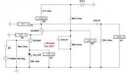
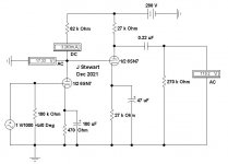
Here are the two driver circuits in plain, ordinary language so that everyone can see what is happening.
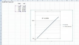
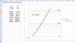
I've added the spread sheet of the forward curve of a LED I ran several years ago.
I general SS diodes are square law in forward conduction while vacuum tubes obey a 3/2 power curve.
The question then becomes does the SS diode enhance the sound & performance. Or the other way round.
For sure there will be a difference, I've never seen a study on what the result is. Anyone seen something?
Attachments
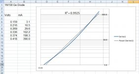
HiHere are two more forward curves for SS diodes. Quite a few others in the collection, some of which are common.
I have just built the Skunkie design and found the cascode biasing too bright for my horns. I changed the led and bias resistor to a 680r bypassed with a 100uf polypropylene cap and it sounds sooooo much nicer.
Hi
I have just built the Skunkie design and found the cascode biasing too bright for my horns. I changed the led and bias resistor to a 680r bypassed with a 100uf polypropylene cap and it sounds sooooo much nicer.
I originally built it with a resistor/bypass cap bias and for my room/speakers/source the LED/resistor sounded better to me. Definitely this is a place you can voice the amp to your use!
The main change in these two circuits doesn't come from the way the driver is biased, it comes from going from a cascade to a cascode.
Count me in as another who prefers the classic resistor and bypass. Bypass caps in my case are DC Link Kemet 40uF. I've tried solid state options like SIC diodes but always found them a little edgy, which I don't get with a resistor.
Glass-packaged diodes, and any kind of LED should be shielded from (flickering) ambient lighting, also, if the chassis does not do it.
I know that the purists will not approve this .
I want to use regulated B+ for the 6sn7 and 300B tubes.
I will use LR8 high voltage regulator for 6sn7 .
With regard to B+ of 435V for 300B, l intend to build these Pete Millet Maida regulator ?
See attached
My questions
1)Can I substitute Lm317 HV by LM 317 ?
2) Can l replace Q1, FQPF2N70 by IRF 840 ?
Thanks
Attachments
Regulating the driver supply may be successful; regulating the anode supply for a 300B is much more difficult. Using series-regulator in a power stage can easily degrade the sound, unless you are very well equipped to optimise it. Using kludgy architectures like the Maida is very likely to sound bad.
The voltage handling required of the semiconductors must account for transients, including a startup and shutdown - and a 500V FET in a 435V output will be far too close. the power handling & heatsinking must accommodate the ±10% likely range of the Line/mains voltage, and handle overcurrent events.
The voltage handling required of the semiconductors must account for transients, including a startup and shutdown - and a 500V FET in a 435V output will be far too close. the power handling & heatsinking must accommodate the ±10% likely range of the Line/mains voltage, and handle overcurrent events.
The FQPF2N70 in that schematic is represented by a P-channel symbol, but the FQPF2N70 is an N-channel FET (does not inspire confidence). If you build it, take extra care that the pinout is assigned correctly!
Is this feasible ?
Use one 12v 50 w Meanwell Ac to dc adapter to power one 6SN7 and one 300B heaters? The adapter output can be adjusted by about 10 per cent
Use 10R 5W dropping resistor for 6SN7 heater and 5R 5W dropping resistor for 300B heater .
Heater current for driver tube is 600ma . 6.3 v and 5v 1.3 amp for 300 B tube
Please advice
- Home
- Amplifiers
- Tubes / Valves
- Skunkie Designs 300B