In theory the 124B should be ok. It can output 27dBu (i.e. 17.3 V rms). Distortion from datasheet looks good but it's for SE:SE case. In SE : PP it will depend on how the balance is obtained (i.e. how much phase shift unbalance it really has). Overall phase shift itself looks high already from 2-3 KHz because of its high leakage inductance. As input transformer it might be less of a problem because signal level is lower and then there is the driver stage in the mix.How about this for a basic design - filament bias 2P29L? I have 124b, also Lundahl LL1660/18mA, Lundahl LL1635/PP
View attachment 1160468
For reference, the Sowter 1475 has less than 1 deg phase shift unbalance but it's a double chamber winding....
The Lundahl 1660 has double coil and so starting from a good position. Phase splitting operation is among suggested applications and the 2P29L has the right plate resistance as recommended by Lundahl. It's also gapped for DC so you can avoid the capacitor.
The LL1635 will NOT work. Already tried.. SE to SE or PP to PP only and it's not even great for these two applications.....
Last edited:
Andy- here is something from the distant past & still used often today,How about this for a basic design -
Not the whole thing, just the method used where the 6N7 is driving the PP IT in the article on p21. Lots of history in these Olde Magazines.👍
https://worldradiohistory.com/Archive-All-Audio/Archive-Audio/40s/Audio-1948-Mar.pdf

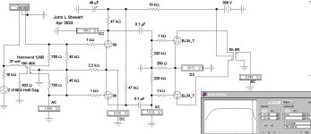
Andy, you're better off with a purely PP (not differential) design with input transformer for phase splitting. You can retain your preferred filament bias approach by paralleling the cathodes for the input tubes. If you insist on using 124B and if you can afford to lose a touch of gain, you can reverse the input transformer and using half of the winding for 22.5K:10K or 1.5:1 step-down and the bandwidth can be improved. 3:1 step-down might lose too much gain. Of course you can always use a different transformer with 1:1 ratio. There's no free lunch in transformer, the lower the impedance the wider the bandwidth and depending on the source impedance (or driving impedance). Example below:

You can also add a phase switch as an extra feature at the input by choosing whichever primary wire with center tap grounded. Of course if you want to be purist about it you can always use two RCA input, one in phase and one inverted phase. Just a suggestion.

You can also add a phase switch as an extra feature at the input by choosing whichever primary wire with center tap grounded. Of course if you want to be purist about it you can always use two RCA input, one in phase and one inverted phase. Just a suggestion.
How about this for a basic design - filament bias 2P29L?
Is worth it?

My experience with 30 tubes indicates that acoustic pickup through the air is significant enough to cause microphonics even if the both the tube socket mounting and the chassis are set up to damp vibration. The tube's envelope transfers enough vibration to the internals to be a problem. My thought is that the envelope needs to be isolated from acoustic energy in the room as well. Putting the 30 tubes in an enclosure is one way to do this. I have experimented with placing jars over 30 tubes, and this did help. Isolation mounting the socket within an enclosure that also isolates the tube from airbound vibration should allow for even overly microphonic tubes to be useable. Adding mass to the chassis and starving the filaments filaments should help as well.
After reading these comments I popped some 30s into my current breadboard setup last night and I just listened to them again. I'm not having any issues with microphonics in normal operation.Rubber mounting alone probably isn't enough. But mass combined with rubber mounting is probably the best you can get. I've thought of taking a slab of 1.5 inch thick granite or marble, wet drill the socket holes in that with rubber under the saddles as well. Then have rubber feet under that slab as well. A 1.5 inch slab from your local kitchen granite store 17 inches x 12 inches would weigh about 31 pounds, 14 kgs. That much mass will not pick up vibrations easily. Whereas a hollow aluminum chassis is basically like mounting the tubes on a drum head! I gave up on that.
I have 5 of these, all NOS military tubes from 1944. Just holding them up to my ear and tapping them I can hear differences in ringing. Using the two that sounded the least microphonic, I can hear it through the speakers if I tap them but it's not sustained and when playing music I hear no issues. The other way I test is to play music louder than normal and then pause the signal to see if there is any residual ringing. No issue there either.
So just now I put in the two that seem to have the most microphonics. Tapping the glass with the amp on and one rings considerably more than the other. But with music playing, no issues, and doing an abrupt pause I also heard no residual sound at all.
These tubes are about 24" away from the speakers at about a 45° angle. Breadboard and speakers are sitting on the same table, which is very solid. No damping at all on the sockets or the tubes themselves. The only damping is a few super thin (~1mm?) pieces of non-skid material that are placed under the breadboard to keep it from sliding around.
Unlike my normal listening setup, my breadboard setup places the tubes in front of, and much closer to, the speakers. So if there are issues with microphonics I would expect them to be more audible in this situation.
The freq response of the 124D & others in these curves is the bare bones result in the test cct.
When installed in a typical cct it may not perform as well.
When I looked at the 124 specs I wasn't so concerned about the 15k limit as I can't hear anything over that at my age anyway. And I suspect that most others here can't either. What I found more worrisome was the lower limit of 150Hz. I can definitely hear way below that.This Sim shews the Hammond IT makes it out to more than 50 KHz.👍
Charlie: Interesting. I suppose it’s going to be room and setup placement dependant. In my case, using the 30/EL84 amp I built, which does a mediocre job of isolating the 30 tubes, most 30 tubes will audibly ring through the speakers for a second or so beyond the point of turning the music off. I have a pair of Klipschorns and a pair of La Scalas in my listening room. The room is 16’X25’ with a 7’2” ceiling. Cinder block walls, a tile floor and drywall ceiling. There is a large thick pile carpet on about a third of the floor, one of the short walls, opposite the Khorns, is entirely covered with 6” of mineral wool covered by fabric, and there are 8 sound absorbing panels arranged around the room. The room is fairly well damped with respect to reverberation/echo according to REW measurements. My equipment stand is midway on one of the long walls opposite the La Scalas, which are set up about 9 feet apart. The ringing happens whether I use the Khorns or La Scalas, and is volume and frequency dependant. It sounds like the 30s all ring at around the same frequency. With sustained notes at that frequency, the volume does not need to be very high to cause the ringing. I do need to revisit the build. I’ll probably rehouse it into a more massive and anti resonant chassis, and try to add a box of some sort so the 30s are isolated from airborne vibrations. The amp does sound very nice otherwise. It could be that my amp does a very bad job of isolating the 30s, despite my efforts. I’ll try fixing it.After reading these comments I popped some 30s into my current breadboard setup last night and I just listened to them again. I'm not having any issues with microphonics in normal operation.
I have 5 of these, all NOS military tubes from 1944. Just holding them up to my ear and tapping them I can hear differences in ringing. Using the two that sounded the least microphonic, I can hear it through the speakers if I tap them but it's not sustained and when playing music I hear no issues. The other way I test is to play music louder than normal and then pause the signal to see if there is any residual ringing. No issue there either.
So just now I put in the two that seem to have the most microphonics. Tapping the glass with the amp on and one rings considerably more than the other. But with music playing, no issues, and doing an abrupt pause I also heard no residual sound at all.
These tubes are about 24" away from the speakers at about a 45° angle. Breadboard and speakers are sitting on the same table, which is very solid. No damping at all on the sockets or the tubes themselves. The only damping is a few super thin (~1mm?) pieces of non-skid material that are placed under the breadboard to keep it from sliding around.
Unlike my normal listening setup, my breadboard setup places the tubes in front of, and much closer to, the speakers. So if there are issues with microphonics I would expect them to be more audible in this situation.
Last edited:
Charlie: Is bandwidth signal level dependant? In the case of output transformers, bandwidth on the low end is specified at a particular output level, but at less output bandwidth increases.When I looked at the 124 specs I wasn't so concerned about the 15k limit as I can't hear anything over that at my age anyway. And I suspect that most others here can't either. What I found more worrisome was the lower limit of 150Hz. I can definitely hear way below that.
IMHO it's not "better", than -moderately good- DHT SE amp, and more complicated.You don't like it, Bela? What would you prefer?
This configuration is "textbook example", the cost of components and the final presentation -IMHO- may not be proportional to each other.
If you want good performance, better IT need, than LL1660 (the "normal" version -for me- mediocre product, I used -and hate- it).
Good PP OPT also need, but it's cheaper than its SE equivalent.
In this operating point of EL12n, the limiting factor is the low bias voltage, thus the output power (of simulation) is lower than expected.
I don't like common cathode resistor of power tubes, mainly if not AC blocked. Instead of it I would use independent, blocked cathode resistors.
In this site https://www.diyaudio.com/community/threads/el12n-in-hifi.346273/page-2 #30 post you attached two pictures of EL12 (EL12 and EL12n) trioded curves.
If you have "n" version, higher bias (about -15V, 350V, 50mA) is more appropriate.
It can result higher output power.
I have no idea. Others will comment, I'm sure.Charlie: Is bandwidth signal level dependant? In the case of output transformers, bandwidth on the low end is specified at a particular output level, but at less output bandwidth increases.
Charlie: Is bandwidth signal level dependant?
------------------------
For OPTs the LF is determined by the Source Impedance & the OPT Primary Inductance.
Just as in an auto engine, there is no substitute for cubic inches, more inductance is better.
OTOH, triodes will always do better than pentodes, triode plate resistance is much lower.
For pentodes the number is approx the reflected load impedance, say 5K or whatever vs
the few hundred ohms of a triode.
The HF rolloff is set mostly by the leakage reactance. Less leakage reactance is better.
The tube driving it doesn't matter much. imagine pushing a rope up a hill.
And capacitive reactance of the windings themselves create further problems.
Skin Effect of the wire & Proximity Effect are frequency dependent & increase with frequency.
So there is a fundamental problem for all OPTs. Building in lots of primary inductance needs
a large core & a lot of wire. That results in quite a bit of leakage inductance.
One way out is sectioning of the windings
Your Menne OPTs have been designed with great care to maximize both LF & HF limits.
Not to worry.
And for lesser OPTs, that is where Bode & Black help us with the principles of FB. 👍
Here are PP EL34s, this time driven by PP 30s, same as the cct driven by PP 27s.
Still get ~10 watts of audio with 2V signal in. The performance of the two versions is essentially identical.
Both have some complication with providing power to the filament / heater.
But the 27 doesn't have the microphonic misery of the 30.
Still get ~10 watts of audio with 2V signal in. The performance of the two versions is essentially identical.
Both have some complication with providing power to the filament / heater.
But the 27 doesn't have the microphonic misery of the 30.
Attachments
The Bode plot on the Sim shews the -3db point for the H124D to beWhat I found more worrisome was the lower limit of 150Hz
down around 10 Hz the way it is loaded. Should be OK. Driven hard it would cutoff somewhere higher.😀
The main problem of interstage SE to PP transformers is balance/symmetry. It can easily result in higher distortion than desired already from few KHz and up. The same transformer wired for SE to SE will have much better distortion figures in the higher frequency range. This is not necessarily reflected in frequency response. The higher the signal level the worse. Pretending all the main jobs from the interstage is going to compromise something and that is normally distortion. On the other side, at low frequency, a lower inductance will also be less critical at lower signal level. Again, frequency response is the last of the problems as it's not difficult to get a good one. For example, 40H for 10K input transformer is a good figure. Instead, it's a modest figure for a 10K interstage and is poor for a 10K output transformer.
So, input phase splitting transformer plus differential driver is generally a better solution than SE driver + SE-to-PP interstage transformer. Very likely if low cost transformers are involved.
So, input phase splitting transformer plus differential driver is generally a better solution than SE driver + SE-to-PP interstage transformer. Very likely if low cost transformers are involved.
Last edited:
That’s good enough!The Bode plot on the Sim shews the -3db point for the H124D to be
down around 10 Hz the way it is loaded. Should be OK. Driven hard it would cutoff somewhere higher.😀
45: Splitting at the could work for me as I have a pair of Jensen JT-11P-1 on hand. I’ll need to get the gain up somewhere else with another stage or another transformer.The main problem of interstage SE to PP transformers is balance/symmetry. It can easily result in higher distortion than desired already from few KHz and up. The same transformer wired for SE to SE will have much better distortion figures in the higher frequency range. This is not necessarily reflected in frequency response. The higher the signal level the worse. Pretending all the main jobs from the interstage is going to compromise something and that is normally distortion. On the other side, at low frequency, a lower inductance will also be less critical at lower signal level. Again, frequency response is the last of the problems as it's not difficult to get a good one. For example, 40H for 10K input transformer is a good figure. Instead, it's a modest figure for a 10K interstage and is poor for a 10K output transformer.
So, input phase splitting transformer plus differential driver is generally a better solution than SE driver + SE-to-PP interstage transformer. Very likely if low cost transformers are involved.
I imagine this would also work with a 26 in place of the 27? I do have many, many 27s. Many more 24A too…Here are PP EL34s, this time driven by PP 30s, same as the cct driven by PP 27s.
Still get ~10 watts of audio with 2V signal in. The performance of the two versions is essentially identical.
Both have some complication with providing power to the filament / heater.
But the 27 doesn't have the microphonic misery of the 30.
The Amp would perform about the same as with 27 or 30.I imagine this would also work with a 26 in place of the 27
But the 1,05A filament requirement could be a problem for the heater supply.
You should decide what you want otherwise this discussion can go on forever without a conclusion. With those input transformers, the EL34T at 400V anode voltage and Plitron 8K/8R, one DHT gain stage will result in very low sensitivy. More a so-called booster than power amp. If you are looking for normal power (or even integrated) amp sensitivity then the driver could be 2 differential DC coupled stages in cascade. With 400V+ supply and 48V rms grid-to-grid drive requirement, it can be done without problems. And you also have more freedom with the kind of tubes as the gain of the 2 stage will multiply. You can get there with many more combinations/possibilities. It could be a 12AY7 input DC coupled to the 49, for example. I have tried this combination in SE and it works great, It can provide large swing at low distortion.45: Splitting at the could work for me as I have a pair of Jensen JT-11P-1 on hand. I’ll need to get the gain up somewhere else with another stage or another transformer.
I imagine this would also work with a 26 in place of the 27? I do have many, many 27s. Many more 24A too…
Last edited:
- Home
- Amplifiers
- Tubes / Valves
- Schematic wanted for push-pull triode connected pentode amp with DHT front end