Hi Folks,
I am about to start designing a transmission line bass guitar enclosure with four 10 inch woofers. The drivers will be run full range and smooth midrange is not a necessity but minimising peaks and troughs in the 100hz-250hz range is important.
In the past I have designed and built 2 driver transmission line subwoofers and bass cabinets using AJ Horn to model the driver locations. This is generally one driver at ~1/5 line length with the other at ~1/3 line length
Can anyone provide advice on placement of 4 drivers in a transmission line arrangement?
For reasons surrounding avoiding comb filtering, I would like to avoid placing two drivers side by side at the ~1/5 position and another two side by side at 1/3.
Any advice on how to model 4 Drivers, all at different positions in the line?
Ideally all 4 drivers will be 10 inches apart along the line. Can anyone offer advice on how this will work with nulls and peaks above the fundamental tuning and were the drivers would be ideally placed?
Thanks in advance.
I'd like to avoid that, if at all possible, Dave. Two side by side will give me most of the inherent problems that come with a traditional 4x10 bass cab, which despite being somewhat of a staple bass guitar cabinet, have a few flaws I'd like to deal without, hence the desire to stack all speakers vertically.
Then you'll want to consider the effect along the length, because if you spaced them along the length then you can stall the wave. Develop a geometry that puts them each at a comparable distance along the travelled path.
@AllenB thats exactly the kind of info I need. If having them all in a line might stall the wave, perhaps I need to get my thinking cap on and work.out how to fold the box so that the speakers are at only two points in the box, but aren't side by side on the baffle.
This might be a challenge.
This might be a challenge.

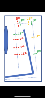
On seeing that you want to use four drivers I would advice locating them to cancel as many modes as they can afford. Using four drivers one can design a quarter wave transmission line that mathematically cancels the 3rd, 5th, 7th and 9th harmonic mode internal standing waves. The 9th mode is a side benefit since it is a multiple of the third. The 11th mode will not be canceled. That most likely won't be a problem to be concerned about.Can anyone offer advice on how this will work with nulls and peaks above the fundamental tuning and were the drivers would be ideally placed?
Thanks in advance.
I will give exact fractions of the acoustic center of the drivers in terms of the acoustic line length measured from the inside of the closed end. Also, the locations will assume a straight line with near zero area discontinuities.
1st driver @ 1/105, 2nd driver @29/105, 3rd driver @ 41/105, and 4th driver @ 71/105. The first driver may require a little imaginative design work to fit properly since it needs to be so close to the closed end.
Please contact if you have any questions concerning
C
Last edited:
Two side by side
Not side by side, but in a vertical line. I did a sketch, looks like unless the line is long you may not be able to fit them (doesn’t in the sketch i made) . But that brings up the ⅓ and 1/5 thing which has always struck me as a guess.
We always choose a Zd (driver offset) that kills the first unwanted harmonic (i am guessing that trying to cancel many will not work, Scott?). You may also have to try HornResp.
dave
hi Cochleus:On seeing that you want to use four drivers I would advice locating them to cancel as many modes as they can afford. Using four drivers one can design a quarter wave transmission line that mathematically cancels the 3rd, 5th, 7th and 9th harmonic mode internal standing waves. The 9th mode is a side benefit since it is a multiple of the third. The 11th mode will not be canceled. That most likely won't be a problem to be concerned about.
I will give exact fractions of the acoustic center of the drivers in terms of the acoustic line length measured from the inside of the closed end. Also, the locations will assume a straight line with near zero area discontinuities.
1st driver @ 1/105, 2nd driver @29/105, 3rd driver @ 41/105, and 4th driver @ 71/105. The first driver may require a little imaginative design work to fit properly since it needs to be so close to the closed end.
Please contact if you have any questions concerning
C
Is this the same as
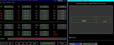
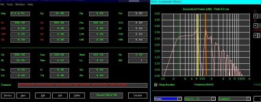
300cm pipe(1/4) 28.8 hz
3/4 @ ~100cm 86.4 hz
5/4 @ ~60cm 144hz
7/4 @ ~ 42.857cm 201.6hz
9/4 @ ~33.33cm 259.2hz
(plus the shift for end correction)?
like:
104.7cm
62.9cm
44.9cm
35cm
I’m a dumb@ss …. I created two ‘upstream’ resonators to hit the 3/4 ~100cm) and 5/4(~60cm) in a 300cm pipe, I created another between them 🙈
Attachments
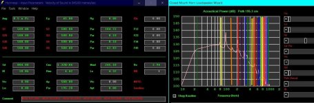
The first driver essentially becomes the closed end of the pipe (driver center @ 1/105=0.01) 😎
The second driver center is at about 83 cm (29/105= 0.28 L from closed end (first driver),
Third driver at about 117 cm (41/105=0.39 L and, the forth @ about 203 cm (71/105=0.68 L).
These points are all simply generated using a modal function: (cos((Pi/2)x(drive point)x(mode number))
The modal function will generate a number between -1 and 1
So placing a driver at some point in the line will generate a number for each mode
In order to cancel that mode another driver is needed placed at a point that zeros the number that he first driver created.
You can also do this with as many drivers you want.
The measurements I give you are for the hypothetical model you posted
C
Last edited:
The first driver being located at the closed end is just an artifact of a four driver system.
If you want a two driver system the drive points move to 2/15 L and 8/15 L from the closed end but, only cancels
the third and fifth modes.
If you want a two driver system the drive points move to 2/15 L and 8/15 L from the closed end but, only cancels
the third and fifth modes.
For a single driver system the drive point moves to 1/3 L (modal function equals zero for mode 3
You can use two drivers if they are spaced equally from the 1/3 point because the modal functions
zero out when you add them together. If you continue spread them further apart equally from the 1/3 point
you get to 2/15 and 8/15 at which the mode 5 cancels along with mode 3 simultaneously.
That's how you get to a four driver system; you spread two apart from 2/15 and 8/15 points equally to arrive at 1/105, 29/105, 41/105 and 71/105.
The 1/105 point actually has a counter point at -!/105 that also works . You can see why if you unfold the quarter wave line into a half wave line.
The previously closed end now becomes the center point with a half wave line.
C
Your welcome. I was saving that nugget just for you 😎
It will at least get you into the ball park with mode controlling.
The drive points will shift with tapered lines. And, higher modes are more effected
with placement errors. I do think the low freqs are the obvious realm of mode controlling.
Let me know if you have luck
or questions.
C
It will at least get you into the ball park with mode controlling.
The drive points will shift with tapered lines. And, higher modes are more effected
with placement errors. I do think the low freqs are the obvious realm of mode controlling.
Let me know if you have luck
or questions.
C
I'll have to look at the patent for specifics but same basic principles at least in part.Can this be sorted Out ‘better’ ?
Using one driver (a fraction of the driver count) where it covers each mode will reduce the overall improvement, it can also change the effective line length potentially moving the modes.
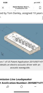
https://audioxpress.com/article/patent-review-bose-transmission-line-loudspeakerI'll have to look at the patent for specifics but same basic principles at least in part.
- Home
- Loudspeakers
- Subwoofers
- Transmission Line with 4 Drivers