Here are some IMD measurements for you guys who were interested. I also took a 31 tone multitone, spikes just above the noise floor is mains harmonics in the measurement chain, amplifier is clean.


@fireanimal
Home run buddy! I'll be sending you a pm in the future when I need some heatsinks and advice! Wolverine is deservingly a monoblock build!
Thanks again for all the hard work!
Best,
Anand.
Home run buddy! I'll be sending you a pm in the future when I need some heatsinks and advice! Wolverine is deservingly a monoblock build!
Thanks again for all the hard work!
Best,
Anand.
It for sure is. Cleanest high power amp I have ever measured. It is like the top of the line opamp on steroids. Spoiler... 1 kHz FFT will be on here shortly. Just finished measuring it with with the notch.
Holy Moly, that's nice! Glad I made mono blocks now.
Hi Guy's, for anyone who is new to this thread I just want to let you all know that there are still some 2nd Group Buy boards available.
@jjs is servicing the USA and Canada regions.
@stuartmp is servicing the other regions.
Please also don't forget that @fireanimal is offering to build and test completed amplifier modules for those who wish to take advantage of this service. PM him if your interested.
@jjs is servicing the USA and Canada regions.
@stuartmp is servicing the other regions.
Please also don't forget that @fireanimal is offering to build and test completed amplifier modules for those who wish to take advantage of this service. PM him if your interested.
Some progress on the first board. Still awaitng a batch of semi's....
.jpeg")


Hi Guys, @Harry3 kindly updated to BOM. Please see the revision table for the updates.
Thanks Harry. 🙏
Thanks Harry. 🙏
fireanimal,
with those measurements, it's hard to believe this is a DIY amp!
with those measurements, it's hard to believe this is a DIY amp!
I believe , the first Wolverine 6 years ago was <5ppm. In fact , the whole "Slewmaster" collection all tested under .001%/ 20k.
With this one we got "anal" with the layout. This layout seems to work well to cancel out what (was) left. Halcro, Nikko , Para sound and Pass
layouts were "observed" to get this one. I could get any of my slewmaster designs to easily outperform ANY OEM , with ease.
OS
PS - the real amp preforms better than the simulation. ??? Even without parasitic L/C and other LT tricks (ideal) ? Let the simulation "deniers" chew on that.
Dear Volverine Team,
I've been following this discussion for a long time and despite all the team's efforts, I still don't feel confident with the project.
I kindly ask you to do square wave tests (step response) and frequency response (-3dB) at 0.3 0.5 and 0.75 Vout max. with non-inductive dummy load. I saw you have all tools to do the job.
Thank you and I hope the result become motivating for me and other interested like me.
Thank you
Here is one scaled 20-20k. Note how linear the phase is 👍

Dear,Dear Volverine Team,
I've been following this discussion for a long time and despite all the team's efforts, I still don't feel confident with the project.
I kindly ask you to do square wave tests (step response) and frequency response (-3dB) at 0.3 0.5 and 0.75 Vout max. with non-inductive dummy load. I saw you have all tools to do the job.
Thank you and I hope the result become motivating for me and other interested like me.
Thank you
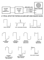
This is a simple and effective test to show the amplifier and its compensation behaviour. It was well explained by Dr. Bora forum user in the past.
By the way, 10KHz is a good frequency to the imput square wave with very fast rise and fall times with no ringing (use correct impedance cable and termination in the generator output).
Thank you again
Last edited:
I do not know if the user 'fireanimal' tryed to answer my question.
Frequency Response showns the -3dB point were the gain start to fall down. This curve must have a phase curve folloing the gain curve. The -3dB point normally changes with the output level. Lower level means highier frequency 3dB point.
Just remenber SACD has 100KHz of bandwith in its specs and some old good quality amplifier used to go near to 500KHz.
it is always useful to show how the test was done by describing applied equipment and the output load.
Another point to remember:I cant measure the upper -3dB point of the wolverine. It is out past 192kHz. Lower -3dB point is 2.5Hz.
I was showing the flatness of the gain curve between 20 and 20k.
When you listem music you have lots of signal, one over the other, and this sum makes the stage details and create the correct audition (you depend of your speaker to get good result). So static tests done with continuos signal must go to highier frequencies in good amplifier.
The square test shows how is the amplifier and feedback behaviour and it is the most revelating test without audition.
Regards
Here is the small and large step response of the Wolverine EF3-4 at 30kHz


In the atached picture you can find some details generated by Dr. Borah long time ago.
Now there are some changes in the best spected square response.
You got a good square answer with your low distoction profile and is like the SIM result I got with the limited information from your schematics.
There are some product review that show what is the best answer by now. I could not find the review to show you as a reference.
Thank you for your time.
Attachments
You are describing basic square wave testing. Andy has shown you a graph at 30Khz....
When one of us gets the time, we will dig out square waves that have been done for 1Khz, 10Khz etc.
When one of us gets the time, we will dig out square waves that have been done for 1Khz, 10Khz etc.
- Home
- Amplifiers
- Solid State
- DIY Class A/B Amp The "Wolverine" build thread