For over a month I have been consumed by Ale's blog https://www.bartola.co.uk/valves/ There is so much resonating reading material that I have been blown away by the amount of detail and knowledge shared. This has inspired me to repeat the Ale’s journey building his 300B amplifier. The lump budget sum is over 5k Euro, yet, being a complete audio fool, I would like to check components suitability before committing to this expenditure. As you can imagine, the list of questions is long, especially for somebody who googles “Voltage drop resistor calculator” on a frequent basis, so I will post questions slowly, module-after-module and we will see where it takes us..
Everybody’s help is very appreciated. I will try not to offend anybody with stupid questions, however, if this happens, please take no offence.
I would also like to ask your opinion, can I post my build excel BOM’s with prices and store links, or that would violate some forum policy? That would be at least useful for some other novice like me trying to make his dream come though.
Fist question list, main board:
Capacitors:
Three resistors per channel, R1 Grid stopper (330R 1/4W 1%), R2 Grid leak (47k 1/8W 5%) and 510 k 1/4W 5%). I think the grid stopper will be the most audible, and a boutique one could be placed there, or maybe I would put all standard metal film resistors here?
Other Misc.

Everybody’s help is very appreciated. I will try not to offend anybody with stupid questions, however, if this happens, please take no offence.
I would also like to ask your opinion, can I post my build excel BOM’s with prices and store links, or that would violate some forum policy? That would be at least useful for some other novice like me trying to make his dream come though.
Fist question list, main board:
Capacitors:
- C1 80uF/900 V. This is a DC link cap. Wima has been hard to source, would a Vishay DC-Link cap do? https://www.vishay.com/docs/26015/mkp1848cdclink.pdf This is shared between left and right channel.
- C2 100nF, 600V. Ale used K40Y-9B paper in oil there. Could a MYFLEX S.A Capacitor: aluminum-polypropylene-paper; 0.1uF; 600VDC; ±5%; be a substitute? Otherwise I need to find a local flea market for similar part.
- C3 100uF Electrolytic. What should be the voltage rating on this?
- C4 WIMA DC LINK very straightforward. This is shared between left and right channel too like C1.
- C5 coupling cap I would like to use the same as C2. Or I should opt for others i.e. Jensen? If somebody can share their views that would be great.
Three resistors per channel, R1 Grid stopper (330R 1/4W 1%), R2 Grid leak (47k 1/8W 5%) and 510 k 1/4W 5%). I think the grid stopper will be the most audible, and a boutique one could be placed there, or maybe I would put all standard metal film resistors here?
Other Misc.
- Tube sockets.. I only worked with Chinese ceramic so far. Would a proper hand carved PTFE with gold pins make a difference and would be recommended?
- Tube biasing.. currently done with 3x C3D02060, which should give me.. ~3 volts? I understand for trials testing, the same could be done with a single LED, or ~200R 5W wire wound bypassed with 220uF/16V electrolytic cap. I would like to prepare and try out different options just for understanding of effect on sound.

My opinion:
DC Link substitution - Yes
Polypropylene for KY40-9B - Yes
C3 voltage - supply is 25V, therefore 35V, 50V, 63V are all acceptable
Grid stop resistors don't conduct current under normal circumstances. Therefore they don't generate noise. Good quality MF is fine
C3D02060 were chosen for consistency and stability, LEDs have a wider spread of foreward voltage drop and their dynamic resistance may not be as low. For development they should be fine, but for final assembly I would recommend the C3D02060.
From my limited testing, WW resistsors produce more harmonic distortion than MF and MOF resistors
I like gold pin sockets when using gold pin tubes. I try to keep mechanical contact materials similar.
My opinion
I can't understad the use of the sand mixed with tubes, mainly where is the 300B
Then 80 uf at 900 Vdc? Why?
https://www.tme.eu/it/details/4.16.10.30.64/condensatori-per-motori/ducati-energia/416103064/ 8.60 eu. each
Then the use of ac for filamentts of 300B allow for me is much better, with an 1 ohm resistor to ground to momitor the current
Appreciate your opinion, yet my aim is to recreate/mimic the project with minimal changes only based on material supply availability. Further modifications will be done on my own to test the impact on sound, like motor run caps etc. Thank youI can't understand the use of the sand mixed with tubes, mainly where is the 300B
One more question on the beads for D3a - there are many resistances available on the market, yet I understand I should aim for the lowest one, like https://www.tme.eu/gb/details/b-01-a1/ferrite-beads/kemet/ is that correct assumption? I attach Ale's cropped picture

AC filament vs Rod Coleman regulators, the difference is like night and day. With AC filaments intermodulation is high with Coleman regulators very low. Hum balance potentiometers will not do anything about it. Standard DC voltage regulation is also NOT going to reduce IMD much but surely better than AC.Then the use of ac for filamentts of 300B allow for me is much better, with an 1 ohm resistor to ground to momitor the current
80 - 200Ω (100MHz) will be enough.One more question on the beads for D3a - there are many resistances available on the market, yet I understand I should aim for the lowest one, like https://www.tme.eu/gb/details/b-01-a1/ferrite-beads/kemet/ is that correct assumption? I attach Ale's cropped picture
Ferrocore FRH035060-A or FRH035080-A; or Richco RRHL35-75-8T52 -- all at TME.eu, if you are shopping there.
You could put a 60Ω bead in the grid, and a higher value in the anode, to make it more robust against oscillation.
But don't put a bead in the cathode - that will degrade the safe margin for stability.
Lo-µ DHTs like 300B should not need a grid stopper, unless the wiring is very badly routed. But the 330Ω (better 100Ω) mounted at the output of the FET follower can improve the stabiity of the FET.R1 Grid stopper (330R 1/4W 1%),
Yes, this is a Real DC-Link. The ca. 5mΩ (>50µF) ESR indicates high-quality and stacked construction, which is the best indicator.C1 80uF/900 V. This is a DC link cap. Wima has been hard to source, would a Vishay DC-Link cap do? https://www.vishay.com/docs/26015/mkp1848cdclink.pdf This is shared between left and right channel.
Stacked construction MKP (Polypropylene) is best for this; OR the smallest DC Link you can find will also be good - capacitance can be 5µF is need be.C2 100nF, 600V. Ale used K40Y-9B paper in oil there.
315V or 400V.C3 100uF Electrolytic. What should be the voltage rating on this?
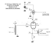
My preference would very much be for Ale's other 300b build.
https://www.bartola.co.uk/valves/2020/07/25/300b-se-amp-47-driver/
This is basically the circuit I use for my 2a3 amp, with some differences.
I know Ale quite well and he liked that circuit - it dates from July 2020. It's DHT end to end, which would be my choice.
https://www.bartola.co.uk/valves/2020/07/25/300b-se-amp-47-driver/
This is basically the circuit I use for my 2a3 amp, with some differences.
- The SUT isn't the Lundahl LL7903, it's the Hammond 1140-LN-C. I think that sounds very good and is much cheaper.
- I use a 10Y instead of the 47. The 47 is good - I've tried it and it sounds nice as well.
- I use filament bias and a resistor load with a straightforward cap coupling (teflon FT-2, 0.1uF) into the grid of the output valve. I left out all the solid state that Ale is so clever at.
I know Ale quite well and he liked that circuit - it dates from July 2020. It's DHT end to end, which would be my choice.
I use similar design (CCS loaded, green LED biased D3a, 100nF V-Cap CuTF capacitor, FET source follower, 300B SE, 5k:8 OPT) for more than a decade.
The quality of C5 is very important. Use there the best capacitor you can afford.
I mostly use teflon capacitors (V-Cap, soviet FT-2, FT-3) for coupling, but it's my taste. Any good copper or silver folie capacitor working well there.
The quality of C5 is very important. Use there the best capacitor you can afford.
I mostly use teflon capacitors (V-Cap, soviet FT-2, FT-3) for coupling, but it's my taste. Any good copper or silver folie capacitor working well there.
Thank you @Rod Coleman for the answer.
Important remark, I though to, as the working voltage will be ~225V315V or 400V.
Noted, Will prepare 100Ohm to test too.300B should not need a grid stopper
Will procure accordingly, thanks for the important details.You could put a 60Ω bead in the grid
Thanks @andyjevans, I will keep that in mind. Will continue to aim for D3a driver, however, I see making multiple driver units later, but there is a lot of work to do before that.My preference would very much be for Ale's other 300b build.
Noted @euro21, thank you.Use there the best capacitor you can afford.
Thank you all for the contribution. This is really encouraging and I am moving to the second set of questions reviewing Ale's project - HT PSU.
1) R2-C7 combo - can I use ready made X2 rated filters (100n+47R), or better to use individual components with ability to "tune"?
2) Hybrid rectifier use used in the project is 6BY5GA tube + UF4007 diodes. I guess this is more of a preference/existing stock questions, and any rectifier design can be used, provided that the end voltage targets are met.
3) Fuses F1 (Mains) and F2. Providing that they are rated for the operating voltage, I understand that F1 Mains can be a slow-blow fuse, and F2 must be fast-acting one (T configuration) so the risk is minimized.
4) Chokes L3-L4 can be a little higher/lover in inductance, provided voltage stabilization is achieved and end voltage requirements are met and current rating is suitable. Its the choke resistance having the most influence in the end voltage.
5) Based on my understanding, C8-C9 will not be working too hard after L3 choke. I still intend to use something with high ripple current rating just for the long life and stability. https://www.tme.eu/lt/details/mal215947151e3/elektrolitiniai-kondensatoriai-snap-in/vishay/
6) C10 (0.1uF PIO) can be skipped altogether? What is the purpose of using paper in oil here? I though C11 is the most audible.
7) INS-1 is there just for indication/safety and is optional.
8) R5 bleed should be tested after assembly that is drains the circuit fast enough (~30-45seconds) for safe operation.
Thank you in advance.
I think you'd get better sound out of a 5U4G and Wolfspeed 1200V Schottky diodes. I've tried 6BY5G and UF4007 and that was my findings. You may not have 5V at 3A though.
Thanks all for the contribution
@andyjevans , I have looked a bit deeper into your suggestion to use VT-25 10A and that has settled into my mind. What tube biasing schematics are you happy with? I see that Ale is quite fond of using unbypassed cathode resistor yet others have a mixed opinion on that.
Noted.5U4G and Wolfspeed 1200V Schottky diodes.
@andyjevans , I have looked a bit deeper into your suggestion to use VT-25 10A and that has settled into my mind. What tube biasing schematics are you happy with? I see that Ale is quite fond of using unbypassed cathode resistor yet others have a mixed opinion on that.
Attachments
10Y/VT25 (or 801a/VT62) has only 8x theoretical gain, so even with 1:4 SUT this tube hasn't enough gain to drive 300B to full power (at 2V RMS input to A1 limit).
@euro21 I am feeling a bit dumb here, as I have researched quite a few VT-25 drivers with 300B output tubes using 1:4 or 1:8 step up and either choke/cap or 1:1 transformer coupling.. so they are simply not briging their 300Bs to the full throttle? I would be quite allright too I guess - never really reach more than 4W output using my speakers.
With 1:8 SUT it has enough gain ... but no free lunch.
The HF -3dB limit will happen soon (usually at about 2x kHz).
High output impedance tubes -as 10Y/801a - requiring high impedance 1:1 IT (high -1xxH- primary inductance), or similar anode choke.
The HF -3dB limit will happen soon (usually at about 2x kHz).
High output impedance tubes -as 10Y/801a - requiring high impedance 1:1 IT (high -1xxH- primary inductance), or similar anode choke.
Last edited:
- Home
- Amplifiers
- Tubes / Valves
- Bartola 300B SE build