6A3sUMMER, thanks for the analysis.
mbrennwa, Output is at an 8 Ohm resistor on the output of the OPT.
Measurements were at the 8Ohm load resistor on the output of the OPT through a resistor divider to parovide 1Vrms at 1W into the soundcard. For higher power levels, I had to change the resistor divider ratio to prevent over-driving the sound card input.
Western Electric had the wisdom to make measurements and calculate the output power of the 300B plate to the load (a resistor; or known primary impedance).
Very tough to do with a resistor, because of the extremely high voltage supply needed to make up for the DC voltage loss of the resistor; and also the extremely large heat in the resistor, high wattage required.
But Western Electric engineers were not stupid, I bet they measured and calculated the 300B plate output power with very well characterized transformer primaries, secondaries, and load resistors; Or using a very well known high impedance choke in parallel with the load resistor (like a 100k ohms choke inductive reactance at 1 kHz in parallel with a 5006 Ohm resistor = 5k Ohms).
That forces the design engineer to include the output transformer insertion loss when designing a 300B power amplifier stage.
Which transformer will he decide to use partly depends on the insertion loss versus how much power he needs from the 300B in order to get the power from the transformer secondary that he wants.
I hope we have solved the basic difference between expected and measured output power.
Last edited:
Thanks, Yes, the 5K at 80ma would be an additional 400V on top of Vak plus Vk and an additional 32W dissipation.
I realized there was something going on between the One Electron with 286R resistance vs the Edcore with 85R primary resistance. The IR losses have to go somewhere (heat), more difficult to calculate/measure would be core losses. I presume these are less than the IR losses, particularly for the One Electron transformer.
Is there any rule of thumb for these core losses?
It would seem that the larger the transformer core the greater the core losses as magnetizing force goes up. This would seem to be a tradeoff in power vs fine detail. If, core losses would act somewhat like noise to the overall signal, possibly obscuring detail?
Or am I reading too much into this?
If you measure at 1KHz 1W, the OPT has to be really bad if it introduces more than 0.1-0.2% THD. A good OPT will introduce less. At such frequency the role of the core is starting to become less and less important.
https://www.sowter.co.uk/specs/sa08.htm
No fancy core, just best quality M6. You can be assured that if THD is declared it's not just for marketing purposes. Very few do that, in most cases of top quality OPTs they do not declare it probably to save time to measure all their products. Time is what dictates most of the cost. Anyway it's 0.05% THD at 1KHz 25W output. That's what I call a good transformer......
No fancy core, just best quality M6. You can be assured that if THD is declared it's not just for marketing purposes. Very few do that, in most cases of top quality OPTs they do not declare it probably to save time to measure all their products. Time is what dictates most of the cost. Anyway it's 0.05% THD at 1KHz 25W output. That's what I call a good transformer......
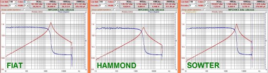
In attach some graph already posted time ago on another thread.
All s S.E. types, similar in Z.
The Fiat is custom made for me, the Hammond is 1627SE and Sowter SA(SF)08
The test is only for trafo without output circuit
The response is, at the end, enough for all three. The THD vs, frequency is differente mainly in the low region.
The reason is in the other graph ( second post)
Attachments
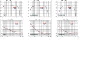

In these plot there is the andament of primary inductance (secondary open) and it is possible to see that where the inductance is reasonable high the THD is lower. The plot is limited to 20 kHz
Is clear tht at 1 kHz the THD of the trafo is extremely low
With the entire circuit a power tube that see a low impedance due the OT limit gives an additional contribution at THD mainly at low frequency( but also at high for different reason)
But take care also at the THD of the input circuit that some time are is not accurate.
Last, the strong selection of tubes is always preferable even not cheaper.
Attachments
Today I went back and took measurements of all six tubes at 8W out (at the load resistor) in fixed bias. The measurements were pretty much the same as for cathode bias with cathode bypass.
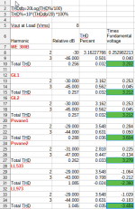
I then looked at the 8.4W output numbers in the WE datasheet with 5K load, and given transformer losses if I have 8W out and 8.4W at the primary of the OPT, then this implies a loss of (8.4-8)/8.4=4.8%.
This is probably a reasonable loss for my transformer, so testing all tubes at 8W at the load should compare favorably to the WE datasheet at 8.4W at the tube which gives 2nd-30dB and 3rd-46dB.
Tube_____2 nd H____3 rd H_____2 nd & 3 rd THD
WE______-30dB_____-46dB_____3.16+0.50=3.66%
GL1_____-30dB_____-45dB_____3.16+0.562=3.72%
GL2_____-30dB_____-45dB_____3.16+0.562=3.72%
Psvane1__-29dB_____-44dB_____3.55+0.631=4.18%
Psvane2__-31dB_____-47dB_____2.82+0.447=3.27%
LL533___-29dB_____-43dB_____3.55+0.71=4.26%
LL973___-29dB_____-44dB_____3.55+0.63=4.18%
Does THD have the same 20% spread as other tube parameters? If so, then we have a spread of 3.05% to 4.39% and all tubes fall within the acceptable range.
Just the luck of the draw that several of my tubes are on the high end.
I look forward to 300-B posting his experience with LinLai 300B tubes.
I think you need to do an RSS to calculate the combined amplitude of the harmonics as THD relative to the fundamental amplitude rather than just adding them together.

Where THDF is a % of the fundamental V1 (assumed 0dB here)
So for example the LL973 the result looks more like 3.6%
You can do RSS directly on the % quoted and it works exactly the same as converting the dB values back to voltage and then doing the calculation.
Where THDF is a % of the fundamental V1 (assumed 0dB here)
So for example the LL973 the result looks more like 3.6%
You can do RSS directly on the % quoted and it works exactly the same as converting the dB values back to voltage and then doing the calculation.
Last edited:
I edited my response not realizing that you had replied - loosing some of the context in your response.. LOL
I confirmed that just doing an RSS on your % worked as well as going back to voltages relative to the fundamental. (I was not 100% sure so I checked on google about RSS of harmonics for THD calcs.)
I confirmed that just doing an RSS on your % worked as well as going back to voltages relative to the fundamental. (I was not 100% sure so I checked on google about RSS of harmonics for THD calcs.)
OK, thanks kevin,. That confirms what I found this site THD and started working on a spreadsheet. Unfortunately, I am used to Excel and am switching to LibreOffice as I am retired. New syntax is going to be fun.
Take the -dB value of the harmonic, Take 10^(-dB/20) to get the percent voltage of the fundamental. Multiply it by the fundimental voltage to get the harmonic voltage. Do this for each harmonic, then take the square root of the sum of the square of each harmonic and finally divide by the voltage of the fundamental.
It will probably be tomorrow before I get the spreadsheet correct and populated.
I can commiserate on libre office, after years of struggling with it and open office I gave up and bought a couple of MS Office licenses and have it on two machines now. Helps keep the very last vestiges of my sanity intact. 🤣
I think you can actually do the RSS directly on your calculated % - I did one of yours and compared calculated from voltage RSS with an RSS of your % - I got the same result. Probably a good idea to confirm though in case I was just lucky. 😀
I use EML 300B in my amps, but have never measured them. The JJ 300B were very good. The EML 20A/B in transformer coupled line amplifier duty are the most linear DHT I have ever measured. (Driving 1K load to 10Vrms) I suppose I really ought to measure the EML 300B in amplifier at some point before I wear them out.
Thanks Kevin,
Personally, I hate Microsoft. Goes back to the days of "Dr Dos" and the dirty tricks uSoft pulled putting them out of business. I will probably go to Linux before I go to Win 11.
I was thinking the same thing WRT to the percent vs the percent times Vout, and then thought "if it sounds too simple, it is probably wrong". I will try both ways and see what I get.
I will attach my spreadsheet when finished, not that it will be anything useful, but people are welcome to fault it.
Waltube, not ignoring your posts, Thanks.
I am trying to understand what it represents and have been searching the web. It appears to be high Z until an inflection point is reached. prior t this it appears inductive and afterwards capacitive if I read the graphs right. Is this where the core no longer plays a significant role in coupling between primary and secondary?
I am trying to understand what it represents and have been searching the web. It appears to be high Z until an inflection point is reached. prior t this it appears inductive and afterwards capacitive if I read the graphs right. Is this where the core no longer plays a significant role in coupling between primary and secondary?
The impedance peak is where the primary inductance resonates with the distributed capacitance of the primary.
The other effects are less of a factor at resonance.
The other effects are less of a factor at resonance.
I think it is best that the power of 8w is measured in primary OT because for different OT the power in the secondary will be variable depending on their yield. My 300b GL amplifier has THD of 2.92% for 8w in the primary at 1Khz and 7.4w in the secondary with a 5.2K home made transformerToday I went back and took measurements of all six tubes at 8W out (at the load resistor) in fixed bias. The measurements were pretty much the same as for cathode bias with cathode bypass.
I then looked at the 8.4W output numbers in the WE datasheet with 5K load, and given transformer losses if I have 8W out and 8.4W at the primary of the OPT, then this implies a loss of (8.4-8)/8.4=4.8%.
This is probably a reasonable loss for my transformer, so testing all tubes at 8W at the load should compare favorably to the WE datasheet at 8.4W at the tube which gives 2nd-30dB and 3rd-46dB.
Tube_____2 nd H____3 rd H_____2 nd & 3 rd THD
WE______-30dB_____-46dB_____3.16+0.50=3.66%
GL1_____-30dB_____-45dB_____3.16+0.562=3.72%
GL2_____-30dB_____-45dB_____3.16+0.562=3.72%
Psvane1__-29dB_____-44dB_____3.55+0.631=4.18%
Psvane2__-31dB_____-47dB_____2.82+0.447=3.27%
LL533___-29dB_____-43dB_____3.55+0.71=4.26%
LL973___-29dB_____-44dB_____3.55+0.63=4.18%
Does THD have the same 20% spread as other tube parameters? If so, then we have a spread of 3.05% to 4.39% and all tubes fall within the acceptable range.
Just the luck of the draw that several of my tubes are on the high end.
I look forward to 300-B posting his experience with LinLai 300B tubes.
It will be boring. Syntax is the same.I am used to Excel and am switching to LibreOffice as I am retired. New syntax is going to be fun.
Or use a good old calculator. You might be faster than the computer takes to boot.
- Home
- Amplifiers
- Tubes / Valves
- 300B with high harmonic distortion