Hi hifi people
Sitting with VituixCAD tweaking on a 2 way filter, and was wondering if impedace fluctuates affects the sound quality in the final result?
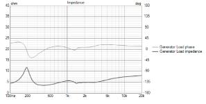
Lets say impeedance goes from 3 up to 18 ohm from 200 hz to 700 hz, and then down again to 4 and then from 3-4 K rises past 20 ohm at the end/20 K.
Or if it goes between 3 and 10-12 ohm, along the entire register ( up and down)
Do i have a benefit in sound if i get the impedance curve like my picturewith 95 % perfect responscurve, or is it better to reach for "100 % perfect" responecurve in VituixCAD?
Its a MTM with 8 ohms mids (paralell to 4 ohm) and a 8 ohm AMT tweeter
Just wondering because sometimes i read about various impedance problems.
/John
Sitting with VituixCAD tweaking on a 2 way filter, and was wondering if impedace fluctuates affects the sound quality in the final result?
Lets say impeedance goes from 3 up to 18 ohm from 200 hz to 700 hz, and then down again to 4 and then from 3-4 K rises past 20 ohm at the end/20 K.
Or if it goes between 3 and 10-12 ohm, along the entire register ( up and down)
Do i have a benefit in sound if i get the impedance curve like my picturewith 95 % perfect responscurve, or is it better to reach for "100 % perfect" responecurve in VituixCAD?
Its a MTM with 8 ohms mids (paralell to 4 ohm) and a 8 ohm AMT tweeter
Just wondering because sometimes i read about various impedance problems.
/John
Attachments

Impedance variations don't really affect the sound quality per se; rather they affect how the crossover components react
Depends on how good a voltage source your amplifier is.
Im using a Krell F.B.I integrated, how i know is stabile down to ca 1 ohm, and the MTM is from 340 hz and up crossing at 2K.
So my amp have no problems with "diffucult" loads, but i was wondering about soundkvalité vs impedance curve.
Is flatter better, and to what degree ?
KEF was famous for (in my book anyway...) having "burner" components in the crossover. "Burner" meaning they did nothing except flatten the impedance looking into the speaker. Belief was amplifiers behave better when loaded into flat Z; their speaker model may see many different amps and they wanted to load them all uniformly, to minimize amp "rolling".
Of course, they used AL-EL caps to do this and as well in the signal pass to the speakers. And of course an AL-EL cap will pass its sound into the audio signal, whether used as a "load" or pass element.
I tried to re-cap one years ago. I gave up on fitting HQ caps into the burner load sections. I assume my result wasnt all it could have been.
Impedance variations don't really affect the sound quality per se; rather they affect how the crossover components react
Getting curious when you answer like that, do you mean that the components valeu can fluctuate due to bigger ohm differences?
Or that the component "leave" a bit of its "signature" in the signalchain?
Also have thought of this:
If a speaker have a 20 ohm impedance between lets say 1 and 3 K, and then dropps to 3 ohm after that, does the amp "leave" the same amount of power in the 1 to 2 K range, and is the SPL constant through the entire frequency range anyway?
Amplifiers often double their power by halving the impedance, and thats why i wonder.
In this case, the impedance characteristic should not be a primary factor.
But heavy, short speaker wires would work best.
Is that due the resistance in the short speaker wires.
And "heavy" in you case means greater mm², like from 2,5 mm² and up ?
Regards/John
No, not in DIY, nor in commercial. Why would it matter more in a DIY speaker - they don't posses any other properties than a commercial speaker. Same electrons and physical laws.
//
//
You know the response is flat as it has been measured. At some frequencies it takes less power to do this.. this is not a problem. A crossover adds 2x6dB with a total of half the power, this is OK. The lower resonance combines mechanical advantage with less current through a higher impedance, this happens to be the right amount.If a speaker have a 20 ohm impedance between lets say 1 and 3 K, and then dropps to 3 ohm after that, does the amp "leave" the same amount of power in the 1 to 2 K range, and is the SPL constant through the entire frequency range anyway?
'Stable' down to 1 ohm doesn't necessarily mean that the distortion specs will be the same as at 8 ohm, where the current variations will be a lot smaller relative to the idle current.
Most of the time I wouldn't worry about the bass impedance peak. Apart from the above note, you may lose more by flattening it with big bi-polar electrolytics. Inductors also have side-effects in real life like transferring energy to other nearby inductors.
As a side note: I don't think I've ever seen anyone experiment directly with manipulating the amount of coupling between air-cored inductors, to fine-tune the response in some beneficial way.
I've done it. Usually when using multiple inductors to make up a larger value. Stacking them tends to give you the better inductance verses resistance tradeoff. It's also a way to fine tune the value.
No, not in DIY, nor in commercial. Why would it matter more in a DIY speaker - they don't posses any other properties than a commercial speaker. Same electrons and physical laws.
That i use the word "DIY" in my title was more a coincidence, i mean in generally when you work att xovers.
( Even if commercial speakers/filters often have a tight budget, and rarely puts "extra-costs" in solutions )
Hi, frequency response is the most audible thing. If you have possibility to tailor the circuit impedance in addition then also look it from the drivers perspective, not just what is the load for the amplifier but also what is the load for the driver.
The driver has back-EMF as voltage source, which makes electronic damping at drivers main resonance happen, and also some distortion higher up. The back-EMF voltage turns into current in the circuit over the impedance thats in series with the driver. The current makes force to the voice coil, the electronic damping, or distortion. To analyze it in VituixCAD replace the voltage source with a resistor of your amplifiers output impedance (~a short) and move the voltage source in series to the driver and now the impedance window shows impedance from drivers perspective. You can short the driver if you wish to see what the contribution of passive network is, to the impedance.
In general its good to have low circuit impedance in series for any driver's main resonance to allow the electronic damping current flow and high series impedance higher up to reduce effect of Le(x) and other sources in driver that make into back-EMF and distortion current over the impedance. Increasing series impedance for the driver reduces the distortion current. Could be audible if you have poor drivers. This also relates to how you mitigate cone breakup, with series or parallel notch. While both do the EQ job the difference is in the circuit impedance and driver generated distortion. Look for "current drive" for a deep dive.
I'm not sure if I hear any difference with the big setup I have as distortion is pretty low anyway. On the other hand smallest change in the frequency response is relatively easy to hear. The system is active so passive parts can be tailored for impedance alone while the frequency response is made with DSP. Not sure how easy or hard it is to apply in passive speaker. For this reason, I encourage to concentrate on the frequency response first and foremost and to let you know there is more to it if you with to dig deeper 🙂 Have fun!
Last edited:
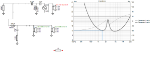
Does that show up on the woofer alone, if you bypass all the parts in the crossover? Its probably some cone resonance, or perhaps even a box resonance. Neither can be dealt with in the crossover if it is property of the physical object(s) which will persist what ever the electronic signal feeding it is. If it shows up as a peak in frequency response you could still reduce it with the crossover and render it inaudible, if it was audible in the first place. If its something audible, best thing to do would be to find out what causes it and try to fix it. If its a box resonance, perhaps adjust damping material, or tighten a screw or something. If its a cone resonance, then swap the driver for better one.For example, if i look att my responsecurve in VituixCAD, i have the same small irregularity both on respons and impedace.
Is that going to be noticeable ?
And can i tackle it some way ?
The driver has back-EMF as voltage source, which makes electronic damping at drivers main resonance happen, and also some distortion higher up. The back-EMF voltage turns into current in the circuit over the impedance thats in series with the driver. The current makes force to the voice coil, the electronic damping, or distortion. To analyze it in VituixCAD replace the voltage source with a resistor of your amplifiers output impedance (~a short) and move the voltage source in series to the driver and now the impedance window shows impedance from drivers perspective.
Thanks for explaining tmuikku, i begain with one thing at the time (so much to try to understand)
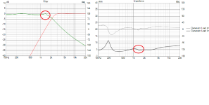
My Krell amp regarding to Stereophiles test have 400k ohms balanced
https://www.stereophile.com/content/krell-fbi-integrated-amplifier-measurements
And if i put a 400.000 ohms resistor in VituixCAD, and move the voltage source it looks like this. (have i understand it right?)
Attachments
You can short the driver if you wish to see what the contribution of passive network is, to the impedance.
Shorted
Does that show up on the woofer alone, if you bypass all the parts in the crossover? Its probably some cone resonance, or perhaps even a box resonance. Neither can be dealt with in the crossover if it is property of the physical object(s) which will persist what ever the electronic signal feeding it is. If it shows up as a peak in frequency response you could still reduce it with the crossover and render it inaudible, if it was audible in the first place. If its something audible, best thing to do would be to find out what causes it and try to fix it. If its a box resonance, perhaps adjust damping material, or tighten a screw or something. If its a cone resonance, then swap the driver for better one.
Yes, it shows also a little without xoverparts.
And also in data specs
Last edited:
'Stable' down to 1 ohm doesn't necessarily mean that the distortion specs will be the same as at 8 ohm, where the current variations will be a lot smaller relative to the idle current.
Most of the time I wouldn't worry about the bass impedance peak. Apart from the above note, you may lose more by flattening it with big bi-polar electrolytics. Inductors also have side-effects in real life like transferring energy to other nearby inductors.
As a side note: I don't think I've ever seen anyone experiment directly with manipulating the amount of coupling between air-cored inductors, to fine-tune the response in some beneficial way.
What about the second impedance peak of bass reflex loads ?
Some dampes it with a LCR, others not like in some Watt looudspeakers (Alexia stereophile measurement for instance). That beginn to be hard to buy 300 uF MKPs for such a job... Also see some half damp it just to reduce the heigth...
That is most probable a mechanical resonance that manifest itself in the impedance trace. You could make a very high Q damping circuit but it wouldn't remove the mechanical problem but it will correct the FR. SO you see problem via the impedance but the root cause is in the driver. When you buy driver, look for the smoothest impedance trace.... problem is that manufactures cheat with smoothed traces.... better look for measurements made by people on the net.For example, if i look att my responsecurve in VituixCAD, i have the same small irregularity both on respons and impedace.
Is that going to be noticeable ?
And can i tackle it some way ?
//
Last edited:
- Home
- Loudspeakers
- Multi-Way
- Is an almost flat impedance curve a big advantage in terms of sound quality in DIY projects