If my assumption of the Forward Voltage drop above is correct, then a rectifier with a significantly lower Peak Reverse Voltage value (e.g. 40V since the expected DC value here is between 6-7V anyway) but a rectifier with a significantly lower Forward drop cannot be appropriate in this position, in the same way 2A with If value? (e.g. CDBHD240-G, the legs are obviously connected with short wires)
That's all you can do in the amp. 236V should give you a bit higher heater voltage though. It also depends on the power tube. 6L6GC variants draw the lowest current so you get the highest possible voltage with those.At least the R70 what was originally 0.47Ohms was changed 0.27Ohms and this resistor was shortcutted at the last measuering where I get the mentioned 6.16V and 5.8V DC heater Voltage value, depends on main AC V value (it is moving sometimes between 236 and 228V)
Hi Ferenc,
I share my experiences on the subject of "low" heater voltage.
A DF210-G 2A version was installed to D7 position instead of the original rectifier (due to the higher current: 2Amper). The Vf value of the DF210-G is considered completely average: 1.1V according to the specifications, and the most recently measured values at points 28-29 (short-circuiting the 0.27 Ohm resistor) were 6.16V. (but it was that it dropped to around 5.8V due to network fluctuations and the passage of time).
I thought this was low and it occurred to me what would happen if I used a "better" rectifier in terms of Vf.
Browsing the specifications and kits, I chose the Vishay LVB1560. By definition, it really doesn't fit where the original one was (huge compared to the other rectifier), but of course I was able to place it with connecting cables.
According to the specifications of this LVB1560, Vf is 0.73V
I was of the opinion that if there really is a "gain" due to the lower Forward Voltage Drop in the new rectifier, then it should appear at the affected points. Fortunately for me, it is. Bridged in the same way (everything unchanged, only the rectifier was replaced), the Heater Voltage in measurement points 28-29 started at 6.56V and stabilized at 6.46V after ~ half an hour. I know this is slightly higher than the 6.3V according to the specifications. (if I remove the short circuit on the resistor and the 0.27 Ohm value works like this, then 28: 6.1V and 29: 6.45) But I put the short circuit back and the heater voltage remained at 6.46V at both points.
Last edited:
If you accept non-PCB friendly solutions then you have more options obviously. Changing rectifier and resistor does not help the power tubes though.
"Changing rectifier and resistor does not help the power tubes though."
Power tubes don't use this H+ rail from D7 rectidfier? So I just hoped all 4 tube are using the same heater rail.
Power tubes don't use this H+ rail from D7 rectidfier? So I just hoped all 4 tube are using the same heater rail.
@Ferenc: thank you for your help again
Another topic:
I already talked about the 807 tube with 6A3sUMMER, but since it can be TU 8200 specific, I will ask the question here as well:
At the 9 o'clock position of the volume control, my 89dB sensitivity monitors (Fyne F500) sound perfectly and with great sound (in fact, loud) in Pentode and UL mode.
And there is no trace of the distortion mentioned earlier in this thread, so much so that there is no audible distortion when the volume is turned up to 12 o'clock.(and the source is on max)
At the same time, when listening to these 807 tubes after switching to Triode mode, serious distortion is already experienced at the same 9 o'clock volume position.
Either I have to turn down the source or the amplifier itself.
I think several people have tried and like to use the 807 in their TU 8200 amplifier, so I would like to ask them if they have experienced something similar?
TKD 2CP-601 model has various type. ex) 10k, 20k, 50k, 100k, Can I know which model can be fit to TU-8200R?TKD 2CP-601
Dear Ferenc,
Thank you very much for your comments. It was appreciated. I considered all cons and prons and decided to install the TKD 601 after I paid so much money for it. And I think I managed it. Hopefuly it will work after I turn the amplifier on. I am attaching some pictures.
Best regards
Milan
Do I understand correctly that the Auto Bias function adjusts the grid voltage relative to the anode/plate? That's why there is a "negative V" value and can we measure this in measurement points 13-14 in the case of the TU 8200R?
At the same time, the difference between measurement points 19-20 (perhaps grid2?) and measurement points 21-22 is only a few V (according to the last measurement, 19-20 /grid2 ? / is higher by 2-4V).
At the same time, the difference between measurement points 19-20 (perhaps grid2?) and measurement points 21-22 is only a few V (according to the last measurement, 19-20 /grid2 ? / is higher by 2-4V).
No. Grid is controlled against cathode with a negative voltage. The cathode of power tubes in TU-8200 is grounded (well, almost) so the normal bias voltage on the grid is between -15 V and -20 V.
The DC difference between screen grid and plate is determined by the DC resistance of the OPT's primary windings x bias current, hence the few volts difference.
The DC difference between screen grid and plate is determined by the DC resistance of the OPT's primary windings x bias current, hence the few volts difference.
Does anyone know the operating point of the 12AU7 in the TU-8200R?
I have a bunch of tubes that I recently tested with a uTracer. Some are slightly unbalanced at higher voltages so trying to determine if they can still be serviceable here or not
I have a bunch of tubes that I recently tested with a uTracer. Some are slightly unbalanced at higher voltages so trying to determine if they can still be serviceable here or not
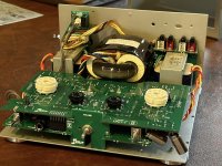
Finished my Elekit TU-8200R this weekend, with some modest upgrades from hifi Collective (As seen on my Unit 1 photo). I haven’t heard a ”stock” version, but mine sounds WAY better than i would have ever expected! This was my first amp build and one of my first DIY projects in general. I can’t say enough about how detailed and clear the manual is (purchased my kit from TubeDepot, a US authorized dealer). It was very easy to follow and assemble. The kit fit and finish is also superb. It fit together with perfect precision, no trouble at all. I’m also grateful to Victor for the support he provided via email. He responded very quickly to my questions. In all, i couldn’t be happier with this build!
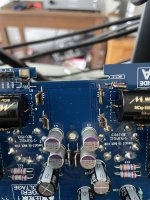
I do not know why you replace the 4 Low ESR cap (C1,C2 and C5, C6).?
It is very dangerous to install C33, C34 and C35 in this maner.
It is very dangerous to install C33, C34 and C35 in this maner.
Victor - For all those C replacements, they were on the Mod list from HiFi Collective - (https://www.hificollective.co.uk/kits/elekit-audio-kits-tu-8200r.html). I'm not sure why Nick chose those particular ones. His instructions say they have to be installed horizontally for clearance. See attached and you can see why. It sure sounds great!
Attachments
I do not recommend to install the cap in this manner
It is more effective to improve the sound by changing the opt to Lundahl LL2777B
It is more effective to improve the sound by changing the opt to Lundahl LL2777B
Because HiFi Collective does not sell Low ESR/Impedance Caps. HiFiCollective parts list is based on what they sell and have they installed and listened to what they selected? Noise is the killer in gear and not using Low ESR/Impedance to what has been designed in the circuit in leu of using SILMIC II (EOL-discontinued) can hinder the outcome. Panasonic FS, FR, Nichicon HE, HW are Low ESR, Low Impedance and would be recommended.Victor - For all those C replacements, they were on the Mod list from HiFi Collective - (https://www.hificollective.co.uk/kits/elekit-audio-kits-tu-8200r.html). I'm not sure why Nick chose those particular ones. His instructions say they have to be installed horizontally for clearance. See attached and you can see why. It sure sounds great!