Just another question: Those LATFET's require much higher gate to source voltages than BJT's. Did anyone try to raise the driver board supply rail voltages by 5 to 10 V above the power devices'?
Best regards!
Best regards!
Hi Kay,
I didnt have any trouble driving them to clipping near the rails with the driver board.
- Dan
I didnt have any trouble driving them to clipping near the rails with the driver board.
- Dan
Did you lokalize where the clipping occured? Was it in the driver board, or was it in the power devices?
I'm asking 'cause I managed to almost double the output power of my Elektor Crescendos with the same Hitachis by raising the driver rails to ±77 V instead of ±70 V as for the LATFET's.
Best regards!
I'm asking 'cause I managed to almost double the output power of my Elektor Crescendos with the same Hitachis by raising the driver rails to ±77 V instead of ±70 V as for the LATFET's.
Best regards!
Well I guess try it out and let us know how you go. I would be interested to see your results.
- Dan
- Dan

Hi,
As I have a surplus of Hitachi / Exicon MOSFETs / large filter caps / large heatsinks / toroidal TFs, I am thinking about making a DH-220C from scratch. However, my TFs have a secondary rating of 55-0-55, giving ~76V rectified DC. As the design is recommeded for up to +/-60VDC I am thinking it will need a few tweaks. Are there any obvious components that won't like the higher voltage? A quick search on the BJTs suggests that they will be fine. Thanks in advance!
As I have a surplus of Hitachi / Exicon MOSFETs / large filter caps / large heatsinks / toroidal TFs, I am thinking about making a DH-220C from scratch. However, my TFs have a secondary rating of 55-0-55, giving ~76V rectified DC. As the design is recommeded for up to +/-60VDC I am thinking it will need a few tweaks. Are there any obvious components that won't like the higher voltage? A quick search on the BJTs suggests that they will be fine. Thanks in advance!
Fyi
We have the DH-220c afe working in dh-500 with +/-90V supplies, a couple of component changes is all and the dh-500c ops pcb is required.
R1,2 need to be 3.6k/3w and use 100v ecaps
We have a writeup on dh-500c and there is a thread on it too if I am not mistaken.
There is also a 3 pair ops pcb for p230 too
Glad to hear you guys like the sound of that design, I can’t hear the difference between Dh-220c and bc-1 although bc-1 is more powerful.
Rick
Last edited:
I would recommend you use Rick Savas/Cordell's boards. HUGH upgrade and fun way to educate and understand the evolution of the hafler topology. Really I think Jim Strickland's name should always be acknowledged in these conversations. His imagination of the jfet cascode with discrete regulated power supply is legendary. ✌️
I think the only thing to take account for in this case will be the drain to source voltage rating (SJ49's and SK134's won't do) and perhaps you'd consider a 3rd pair of power devices.However, my TFs have a secondary rating of 55-0-55, giving ~76V rectified DC.
Best regards!
Anyone out there using the dual die exicon devices in this dH-220c design want to chime in on your experiences? I have not tried myself nor has Bob.
Out of curiosity, I dug out a Maplin (Hitachi Apps-based design, pretty much the HMA-7500 topology) amp that I'd fitted with the 20N20 / 20P20 T03 Exicon devices in 2001 and tested it today. The design was meant for the original SJ / SK Hitachi single die types, as used in the DH-200. I put my observations here: https://www.diyaudio.com/community/...fier-ga28f-construction-thread.257488/page-10
(post 193 in above)
Thank you for the fast response to my enquiry, Rick. I'm away for the weekend and will drop you a line on Monday.
(post 193 in above)
Thank you for the fast response to my enquiry, Rick. I'm away for the weekend and will drop you a line on Monday.
Finished refurbing my DH200. Initially it lacked bass but the rest of the spectrum was very satisfying. DC offset was -17mv and +34mv and bias was settable but unstable.
Replaced virtually all components on both original PC-6 boards, with minor mods; 33pf cap across the Q15 and 16 gates and drains, shielded cable from floated inputs to boards, small bypass caps on the original filter caps (the filter caps tested very well on capacitance and very low ESR), thermal pads instead of paste on ORIGINAL mosfets and thermal switches, 2.2 ohm resistors on both outputs returns to ground, gold plated input and output jacks, IEC mains with ground to chassis, new power switch and finally Rick’s superb soft start circuit. I painstakingly matched all pairs of components and 5550 and 5401 transistors. The only components I did NOT change are Q8,9,11,12 and 13. I ordered a set of Exicon matched (S type) mosfets but haven tried yet since, except for the lacking bass, the amp sounded good. Before listening I scoped both channels just with 1khz sine as a quick function test and found output flat and roughly expected gain from 10hz to 25khz.
DC offset is now 6mv and 11mv, bias is very steady starting at 275ma decreasing to about 265 after an hour of warmup, and no hum.
The listening results however, are disappointing. There is still a distinct lack of bass, mids are clean but the highs are now crystalline sharp and fatiguing. I’m driving highly efficient VOTT A5X speakers, nominally 12 ohm impedance. Volume is not an issue. Borrowing a friend’s McIntosh 75wpc amp for an AB comparison, sounds great.
Before I plug in the new mosfets, I was hoping someone could comment on what else should be looked at first. I know larger filter caps may improve bass, but there is no way the original bass would have been this weak. Could the Qs I did not replace have this kind of effect? I was under the impression they were more associated with bias and power supply than signal.
Thanks in advance for any and all suggestions.
Jeff
Edit: I forgot one other mod. Per one of the mods suggested here, I jumpered pins 8 and 11 and fed output pin 12 through the speaker fuse directly.
Last edited:
I do not have this amp since many years and I had modified it so even more time since the original and the rest of my system was completely different so kind of difficult to comment on the sound….
I think original design bass may not be exceptional but relatively not weak either….
However, I remember it had a bit too much sibilance for my taste…
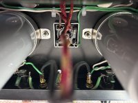
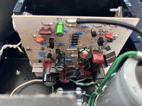
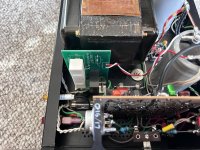
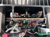
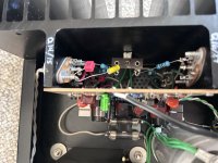
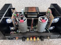
Can you show a picture of your boards and also whole amp to see if there is nothing obvious.
Also, you may have to revisit your expectations as the original dh200 design may not be as “good” as a McIntosh for sound appreciation in the end…😉
Fab
I think original design bass may not be exceptional but relatively not weak either….
However, I remember it had a bit too much sibilance for my taste…
Can you show a picture of your boards and also whole amp to see if there is nothing obvious.
Also, you may have to revisit your expectations as the original dh200 design may not be as “good” as a McIntosh for sound appreciation in the end…😉
Fab
Last edited:
Thanks Fab. I don’t have any unrealistic expectations for the Hafler versus the McIntosh. It was the only known good amp available for an AB comparison. The sibilance was noticeable before the restoration. It got worse after restoration, and now even worse with the Exicon mosfets, though the midrange improved. But still extremely weak bass. I even tried parallel 4700uf caps on the filter caps with no noticeable change. The original caps test at 9900uf and .1 to .2 ohms ESR so I haven’t bothered yet to upgrade them. Supply of decent 20000 or so caps is thin at the moment anyway.
Pics attached, thanks for your response.
Pics attached, thanks for your response.
Attachments
-
 55EC49C4-305E-4F83-99D1-133C6AF1770C.jpeg383.5 KB · Views: 146
 -
 059D94A8-7F20-45F1-9EA6-DA22072AA3B7.jpeg387 KB · Views: 150
 -
 E9D2DC43-23CB-40A6-A292-70B1B9DF4955.jpeg492.2 KB · Views: 159
 -
 12A1C1C9-C70F-4362-A483-5188DB29B5A6.jpeg369.5 KB · Views: 144
 -
 6DFB138F-0015-44AE-88DE-934894F83F0C.jpeg360.5 KB · Views: 147
 -
 E38F917E-0B86-493E-8FE3-9032A2EFBCBA.jpeg620.5 KB · Views: 144
Hi Jeff
I do not see anything obvious from tne picture.
you seem to have a scope and a frequency generator from your previous post. Can you verify the low cutoff frequency at -3dB of the amp Since it should be around 1 Hz. Input cap is supposed to be 10uf according to BOM. Also feedback cap C5 should be 470uf.
EsR of 0.1 to 0.2 ohms is quite high value. It should be about 10 times lower for good big PSU caps.
you may also have very high frequency small oscillation that could cause tonal balance issue…
is it a soft start circuit that you have added to the amp?
Fab
Some corrections and a smoking gun.
The ESR on the PSU caps was when I first got the amp. I reconditioned the caps by charging to 70v for an hour or so and slowly discharging, several times. Testing today on my DE-5000 shows 9400uf and 0.0 ESR at 100hz.
C1 is 10uf non polarized electrolytic though I had been considering a smaller foil cap as recommended a few times in this thread. C5 is 470uf non polarized electrolytic.
I am not well versed on db measurements. My DMM has the feature but its minimum AC measurement spec is 3hz.
So I noted voltages as measured by my scope. The amp‘s left channel is amazingly flat 5hz to over 30Mhz. With a 100mv sine input and a good looking output on the scope, I get the following on the left channel:
1hz. 1.5v
2hz-25Mhz. 1.89v
25Mhz. 1.875v
30-40Mhz. 1.85v
Output wave looks good at 1v input as well.
The right channel has a problem. I will send pics of the scope trace next time I can get to my bench.
- Home
- Amplifiers
- Solid State
- Hafler DH-200/220 Mods